- 您現(xiàn)在的位置:買賣IC網(wǎng) > PDF目錄383737 > PC3S12XEP100J1CALR (飛思卡爾半導(dǎo)體(中國(guó))有限公司) Microcontrollers PDF資料下載
第1頁(yè)第2頁(yè)第3頁(yè)第4頁(yè)第5頁(yè)第6頁(yè)第7頁(yè)第8頁(yè)第9頁(yè)第10頁(yè)第11頁(yè)第12頁(yè)第13頁(yè)第14頁(yè)第15頁(yè)第16頁(yè)第17頁(yè)第18頁(yè)第19頁(yè)第20頁(yè)第21頁(yè)第22頁(yè)第23頁(yè)第24頁(yè)第25頁(yè)第26頁(yè)第27頁(yè)第28頁(yè)第29頁(yè)第30頁(yè)第31頁(yè)第32頁(yè)第33頁(yè)第34頁(yè)第35頁(yè)第36頁(yè)第37頁(yè)第38頁(yè)第39頁(yè)第40頁(yè)第41頁(yè)第42頁(yè)第43頁(yè)第44頁(yè)第45頁(yè)第46頁(yè)第47頁(yè)第48頁(yè)第49頁(yè)第50頁(yè)第51頁(yè)第52頁(yè)第53頁(yè)第54頁(yè)第55頁(yè)第56頁(yè)第57頁(yè)第58頁(yè)第59頁(yè)第60頁(yè)第61頁(yè)第62頁(yè)第63頁(yè)第64頁(yè)第65頁(yè)第66頁(yè)第67頁(yè)第68頁(yè)第69頁(yè)第70頁(yè)第71頁(yè)第72頁(yè)第73頁(yè)第74頁(yè)第75頁(yè)第76頁(yè)第77頁(yè)第78頁(yè)第79頁(yè)第80頁(yè)第81頁(yè)第82頁(yè)第83頁(yè)第84頁(yè)第85頁(yè)第86頁(yè)第87頁(yè)第88頁(yè)第89頁(yè)第90頁(yè)第91頁(yè)第92頁(yè)第93頁(yè)第94頁(yè)第95頁(yè)第96頁(yè)第97頁(yè)第98頁(yè)第99頁(yè)第100頁(yè)第101頁(yè)第102頁(yè)第103頁(yè)第104頁(yè)第105頁(yè)第106頁(yè)第107頁(yè)第108頁(yè)第109頁(yè)第110頁(yè)第111頁(yè)第112頁(yè)第113頁(yè)第114頁(yè)第115頁(yè)第116頁(yè)第117頁(yè)第118頁(yè)第119頁(yè)第120頁(yè)第121頁(yè)第122頁(yè)第123頁(yè)第124頁(yè)第125頁(yè)第126頁(yè)第127頁(yè)第128頁(yè)第129頁(yè)第130頁(yè)第131頁(yè)第132頁(yè)第133頁(yè)第134頁(yè)第135頁(yè)第136頁(yè)第137頁(yè)第138頁(yè)第139頁(yè)第140頁(yè)第141頁(yè)第142頁(yè)第143頁(yè)第144頁(yè)第145頁(yè)第146頁(yè)第147頁(yè)第148頁(yè)第149頁(yè)第150頁(yè)第151頁(yè)第152頁(yè)第153頁(yè)第154頁(yè)第155頁(yè)第156頁(yè)第157頁(yè)第158頁(yè)第159頁(yè)第160頁(yè)第161頁(yè)第162頁(yè)第163頁(yè)第164頁(yè)第165頁(yè)第166頁(yè)第167頁(yè)第168頁(yè)第169頁(yè)當(dāng)前第170頁(yè)第171頁(yè)第172頁(yè)第173頁(yè)第174頁(yè)第175頁(yè)第176頁(yè)第177頁(yè)第178頁(yè)第179頁(yè)第180頁(yè)第181頁(yè)第182頁(yè)第183頁(yè)第184頁(yè)第185頁(yè)第186頁(yè)第187頁(yè)第188頁(yè)第189頁(yè)第190頁(yè)第191頁(yè)第192頁(yè)第193頁(yè)第194頁(yè)第195頁(yè)第196頁(yè)第197頁(yè)第198頁(yè)第199頁(yè)第200頁(yè)第201頁(yè)第202頁(yè)第203頁(yè)第204頁(yè)第205頁(yè)第206頁(yè)第207頁(yè)第208頁(yè)第209頁(yè)第210頁(yè)第211頁(yè)第212頁(yè)第213頁(yè)第214頁(yè)第215頁(yè)第216頁(yè)第217頁(yè)第218頁(yè)第219頁(yè)第220頁(yè)第221頁(yè)第222頁(yè)第223頁(yè)第224頁(yè)第225頁(yè)第226頁(yè)第227頁(yè)第228頁(yè)第229頁(yè)第230頁(yè)第231頁(yè)第232頁(yè)第233頁(yè)第234頁(yè)第235頁(yè)第236頁(yè)第237頁(yè)第238頁(yè)第239頁(yè)第240頁(yè)第241頁(yè)第242頁(yè)第243頁(yè)第244頁(yè)第245頁(yè)第246頁(yè)第247頁(yè)第248頁(yè)第249頁(yè)第250頁(yè)第251頁(yè)第252頁(yè)第253頁(yè)第254頁(yè)第255頁(yè)第256頁(yè)第257頁(yè)第258頁(yè)第259頁(yè)第260頁(yè)第261頁(yè)第262頁(yè)第263頁(yè)第264頁(yè)第265頁(yè)第266頁(yè)第267頁(yè)第268頁(yè)第269頁(yè)第270頁(yè)第271頁(yè)第272頁(yè)第273頁(yè)第274頁(yè)第275頁(yè)第276頁(yè)第277頁(yè)第278頁(yè)第279頁(yè)第280頁(yè)第281頁(yè)第282頁(yè)第283頁(yè)第284頁(yè)第285頁(yè)第286頁(yè)第287頁(yè)第288頁(yè)第289頁(yè)第290頁(yè)第291頁(yè)第292頁(yè)第293頁(yè)第294頁(yè)第295頁(yè)第296頁(yè)第297頁(yè)第298頁(yè)第299頁(yè)第300頁(yè)第301頁(yè)第302頁(yè)第303頁(yè)第304頁(yè)第305頁(yè)第306頁(yè)第307頁(yè)第308頁(yè)第309頁(yè)第310頁(yè)第311頁(yè)第312頁(yè)第313頁(yè)第314頁(yè)第315頁(yè)第316頁(yè)第317頁(yè)第318頁(yè)第319頁(yè)第320頁(yè)第321頁(yè)第322頁(yè)第323頁(yè)第324頁(yè)第325頁(yè)第326頁(yè)第327頁(yè)第328頁(yè)第329頁(yè)第330頁(yè)第331頁(yè)第332頁(yè)第333頁(yè)第334頁(yè)第335頁(yè)第336頁(yè)第337頁(yè)第338頁(yè)第339頁(yè)第340頁(yè)第341頁(yè)第342頁(yè)第343頁(yè)第344頁(yè)第345頁(yè)第346頁(yè)第347頁(yè)第348頁(yè)第349頁(yè)第350頁(yè)第351頁(yè)第352頁(yè)第353頁(yè)第354頁(yè)第355頁(yè)第356頁(yè)第357頁(yè)第358頁(yè)第359頁(yè)第360頁(yè)第361頁(yè)第362頁(yè)第363頁(yè)第364頁(yè)第365頁(yè)第366頁(yè)第367頁(yè)第368頁(yè)第369頁(yè)第370頁(yè)第371頁(yè)第372頁(yè)第373頁(yè)第374頁(yè)第375頁(yè)第376頁(yè)第377頁(yè)第378頁(yè)第379頁(yè)第380頁(yè)第381頁(yè)第382頁(yè)第383頁(yè)第384頁(yè)第385頁(yè)第386頁(yè)第387頁(yè)第388頁(yè)第389頁(yè)第390頁(yè)第391頁(yè)第392頁(yè)第393頁(yè)第394頁(yè)第395頁(yè)第396頁(yè)第397頁(yè)第398頁(yè)第399頁(yè)第400頁(yè)第401頁(yè)第402頁(yè)第403頁(yè)第404頁(yè)第405頁(yè)第406頁(yè)第407頁(yè)第408頁(yè)第409頁(yè)第410頁(yè)第411頁(yè)第412頁(yè)第413頁(yè)第414頁(yè)第415頁(yè)第416頁(yè)第417頁(yè)第418頁(yè)第419頁(yè)第420頁(yè)第421頁(yè)第422頁(yè)第423頁(yè)第424頁(yè)第425頁(yè)第426頁(yè)第427頁(yè)第428頁(yè)第429頁(yè)第430頁(yè)第431頁(yè)第432頁(yè)第433頁(yè)第434頁(yè)第435頁(yè)第436頁(yè)第437頁(yè)第438頁(yè)第439頁(yè)第440頁(yè)第441頁(yè)第442頁(yè)第443頁(yè)第444頁(yè)第445頁(yè)第446頁(yè)第447頁(yè)第448頁(yè)第449頁(yè)第450頁(yè)第451頁(yè)第452頁(yè)第453頁(yè)第454頁(yè)第455頁(yè)第456頁(yè)第457頁(yè)第458頁(yè)第459頁(yè)第460頁(yè)第461頁(yè)第462頁(yè)第463頁(yè)第464頁(yè)第465頁(yè)第466頁(yè)第467頁(yè)第468頁(yè)第469頁(yè)第470頁(yè)第471頁(yè)第472頁(yè)第473頁(yè)第474頁(yè)第475頁(yè)第476頁(yè)第477頁(yè)第478頁(yè)第479頁(yè)第480頁(yè)第481頁(yè)第482頁(yè)第483頁(yè)第484頁(yè)第485頁(yè)第486頁(yè)第487頁(yè)第488頁(yè)第489頁(yè)第490頁(yè)第491頁(yè)第492頁(yè)第493頁(yè)第494頁(yè)第495頁(yè)第496頁(yè)第497頁(yè)第498頁(yè)第499頁(yè)第500頁(yè)第501頁(yè)第502頁(yè)第503頁(yè)第504頁(yè)第505頁(yè)第506頁(yè)第507頁(yè)第508頁(yè)第509頁(yè)第510頁(yè)第511頁(yè)第512頁(yè)第513頁(yè)第514頁(yè)第515頁(yè)第516頁(yè)第517頁(yè)第518頁(yè)第519頁(yè)第520頁(yè)第521頁(yè)第522頁(yè)第523頁(yè)第524頁(yè)第525頁(yè)第526頁(yè)第527頁(yè)第528頁(yè)第529頁(yè)第530頁(yè)第531頁(yè)第532頁(yè)第533頁(yè)第534頁(yè)第535頁(yè)第536頁(yè)第537頁(yè)第538頁(yè)第539頁(yè)第540頁(yè)第541頁(yè)第542頁(yè)第543頁(yè)第544頁(yè)第545頁(yè)第546頁(yè)第547頁(yè)第548頁(yè)第549頁(yè)第550頁(yè)第551頁(yè)第552頁(yè)第553頁(yè)第554頁(yè)第555頁(yè)第556頁(yè)第557頁(yè)第558頁(yè)第559頁(yè)第560頁(yè)第561頁(yè)第562頁(yè)第563頁(yè)第564頁(yè)第565頁(yè)第566頁(yè)第567頁(yè)第568頁(yè)第569頁(yè)第570頁(yè)第571頁(yè)第572頁(yè)第573頁(yè)第574頁(yè)第575頁(yè)第576頁(yè)第577頁(yè)第578頁(yè)第579頁(yè)第580頁(yè)第581頁(yè)第582頁(yè)第583頁(yè)第584頁(yè)第585頁(yè)第586頁(yè)第587頁(yè)第588頁(yè)第589頁(yè)第590頁(yè)第591頁(yè)第592頁(yè)第593頁(yè)第594頁(yè)第595頁(yè)第596頁(yè)第597頁(yè)第598頁(yè)第599頁(yè)第600頁(yè)第601頁(yè)第602頁(yè)第603頁(yè)第604頁(yè)第605頁(yè)第606頁(yè)第607頁(yè)第608頁(yè)第609頁(yè)第610頁(yè)第611頁(yè)第612頁(yè)第613頁(yè)第614頁(yè)第615頁(yè)第616頁(yè)第617頁(yè)第618頁(yè)第619頁(yè)第620頁(yè)第621頁(yè)第622頁(yè)第623頁(yè)第624頁(yè)第625頁(yè)第626頁(yè)第627頁(yè)第628頁(yè)第629頁(yè)第630頁(yè)第631頁(yè)第632頁(yè)第633頁(yè)第634頁(yè)第635頁(yè)第636頁(yè)第637頁(yè)第638頁(yè)第639頁(yè)第640頁(yè)第641頁(yè)第642頁(yè)第643頁(yè)第644頁(yè)第645頁(yè)第646頁(yè)第647頁(yè)第648頁(yè)第649頁(yè)第650頁(yè)第651頁(yè)第652頁(yè)第653頁(yè)第654頁(yè)第655頁(yè)第656頁(yè)第657頁(yè)第658頁(yè)第659頁(yè)第660頁(yè)第661頁(yè)第662頁(yè)第663頁(yè)第664頁(yè)第665頁(yè)第666頁(yè)第667頁(yè)第668頁(yè)第669頁(yè)第670頁(yè)第671頁(yè)第672頁(yè)第673頁(yè)第674頁(yè)第675頁(yè)第676頁(yè)第677頁(yè)第678頁(yè)第679頁(yè)第680頁(yè)第681頁(yè)第682頁(yè)第683頁(yè)第684頁(yè)第685頁(yè)第686頁(yè)第687頁(yè)第688頁(yè)第689頁(yè)第690頁(yè)第691頁(yè)第692頁(yè)第693頁(yè)第694頁(yè)第695頁(yè)第696頁(yè)第697頁(yè)第698頁(yè)第699頁(yè)第700頁(yè)第701頁(yè)第702頁(yè)第703頁(yè)第704頁(yè)第705頁(yè)第706頁(yè)第707頁(yè)第708頁(yè)第709頁(yè)第710頁(yè)第711頁(yè)第712頁(yè)第713頁(yè)第714頁(yè)第715頁(yè)第716頁(yè)第717頁(yè)第718頁(yè)第719頁(yè)第720頁(yè)第721頁(yè)第722頁(yè)第723頁(yè)第724頁(yè)第725頁(yè)第726頁(yè)第727頁(yè)第728頁(yè)第729頁(yè)第730頁(yè)第731頁(yè)第732頁(yè)第733頁(yè)第734頁(yè)第735頁(yè)第736頁(yè)第737頁(yè)第738頁(yè)第739頁(yè)第740頁(yè)第741頁(yè)第742頁(yè)第743頁(yè)第744頁(yè)第745頁(yè)第746頁(yè)第747頁(yè)第748頁(yè)第749頁(yè)第750頁(yè)第751頁(yè)第752頁(yè)第753頁(yè)第754頁(yè)第755頁(yè)第756頁(yè)第757頁(yè)第758頁(yè)第759頁(yè)第760頁(yè)第761頁(yè)第762頁(yè)第763頁(yè)第764頁(yè)第765頁(yè)第766頁(yè)第767頁(yè)第768頁(yè)第769頁(yè)第770頁(yè)第771頁(yè)第772頁(yè)第773頁(yè)第774頁(yè)第775頁(yè)第776頁(yè)第777頁(yè)第778頁(yè)第779頁(yè)第780頁(yè)第781頁(yè)第782頁(yè)第783頁(yè)第784頁(yè)第785頁(yè)第786頁(yè)第787頁(yè)第788頁(yè)第789頁(yè)第790頁(yè)第791頁(yè)第792頁(yè)第793頁(yè)第794頁(yè)第795頁(yè)第796頁(yè)第797頁(yè)第798頁(yè)第799頁(yè)第800頁(yè)第801頁(yè)第802頁(yè)第803頁(yè)第804頁(yè)第805頁(yè)第806頁(yè)第807頁(yè)第808頁(yè)第809頁(yè)第810頁(yè)第811頁(yè)第812頁(yè)第813頁(yè)第814頁(yè)第815頁(yè)第816頁(yè)第817頁(yè)第818頁(yè)第819頁(yè)第820頁(yè)第821頁(yè)第822頁(yè)第823頁(yè)第824頁(yè)第825頁(yè)第826頁(yè)第827頁(yè)第828頁(yè)第829頁(yè)第830頁(yè)第831頁(yè)第832頁(yè)第833頁(yè)第834頁(yè)第835頁(yè)第836頁(yè)第837頁(yè)第838頁(yè)第839頁(yè)第840頁(yè)第841頁(yè)第842頁(yè)第843頁(yè)第844頁(yè)第845頁(yè)第846頁(yè)第847頁(yè)第848頁(yè)第849頁(yè)第850頁(yè)第851頁(yè)第852頁(yè)第853頁(yè)第854頁(yè)第855頁(yè)第856頁(yè)第857頁(yè)第858頁(yè)第859頁(yè)第860頁(yè)第861頁(yè)第862頁(yè)第863頁(yè)第864頁(yè)第865頁(yè)第866頁(yè)第867頁(yè)第868頁(yè)第869頁(yè)第870頁(yè)第871頁(yè)第872頁(yè)第873頁(yè)第874頁(yè)第875頁(yè)第876頁(yè)第877頁(yè)第878頁(yè)第879頁(yè)第880頁(yè)第881頁(yè)第882頁(yè)第883頁(yè)第884頁(yè)第885頁(yè)第886頁(yè)第887頁(yè)第888頁(yè)第889頁(yè)第890頁(yè)第891頁(yè)第892頁(yè)第893頁(yè)第894頁(yè)第895頁(yè)第896頁(yè)第897頁(yè)第898頁(yè)第899頁(yè)第900頁(yè)第901頁(yè)第902頁(yè)第903頁(yè)第904頁(yè)第905頁(yè)第906頁(yè)第907頁(yè)第908頁(yè)第909頁(yè)第910頁(yè)第911頁(yè)第912頁(yè)第913頁(yè)第914頁(yè)第915頁(yè)第916頁(yè)第917頁(yè)第918頁(yè)第919頁(yè)第920頁(yè)第921頁(yè)第922頁(yè)第923頁(yè)第924頁(yè)第925頁(yè)第926頁(yè)第927頁(yè)第928頁(yè)第929頁(yè)第930頁(yè)第931頁(yè)第932頁(yè)第933頁(yè)第934頁(yè)第935頁(yè)第936頁(yè)第937頁(yè)第938頁(yè)第939頁(yè)第940頁(yè)第941頁(yè)第942頁(yè)第943頁(yè)第944頁(yè)第945頁(yè)第946頁(yè)第947頁(yè)第948頁(yè)第949頁(yè)第950頁(yè)第951頁(yè)第952頁(yè)第953頁(yè)第954頁(yè)第955頁(yè)第956頁(yè)第957頁(yè)第958頁(yè)第959頁(yè)第960頁(yè)第961頁(yè)第962頁(yè)第963頁(yè)第964頁(yè)第965頁(yè)第966頁(yè)第967頁(yè)第968頁(yè)第969頁(yè)第970頁(yè)第971頁(yè)第972頁(yè)第973頁(yè)第974頁(yè)第975頁(yè)第976頁(yè)第977頁(yè)第978頁(yè)第979頁(yè)第980頁(yè)第981頁(yè)第982頁(yè)第983頁(yè)第984頁(yè)第985頁(yè)第986頁(yè)第987頁(yè)第988頁(yè)第989頁(yè)第990頁(yè)第991頁(yè)第992頁(yè)第993頁(yè)第994頁(yè)第995頁(yè)第996頁(yè)第997頁(yè)第998頁(yè)第999頁(yè)第1000頁(yè)第1001頁(yè)第1002頁(yè)第1003頁(yè)第1004頁(yè)第1005頁(yè)第1006頁(yè)第1007頁(yè)第1008頁(yè)第1009頁(yè)第1010頁(yè)第1011頁(yè)第1012頁(yè)第1013頁(yè)第1014頁(yè)第1015頁(yè)第1016頁(yè)第1017頁(yè)第1018頁(yè)第1019頁(yè)第1020頁(yè)第1021頁(yè)第1022頁(yè)第1023頁(yè)第1024頁(yè)第1025頁(yè)第1026頁(yè)第1027頁(yè)第1028頁(yè)第1029頁(yè)第1030頁(yè)第1031頁(yè)第1032頁(yè)第1033頁(yè)第1034頁(yè)第1035頁(yè)第1036頁(yè)

Chapter 2 Port Integration Module (S12XEPIMV1)
MC9S12XE-Family Reference Manual , Rev. 1.07
170
Freescale Semiconductor
NOTE
Due to internal synchronization circuits, it can take up to 2 bus clock cycles
until the correct value is read on PTF or PTIF registers, when changing the
DDRF register.
2.3.104 Port F Reduced Drive Register (RDRF)
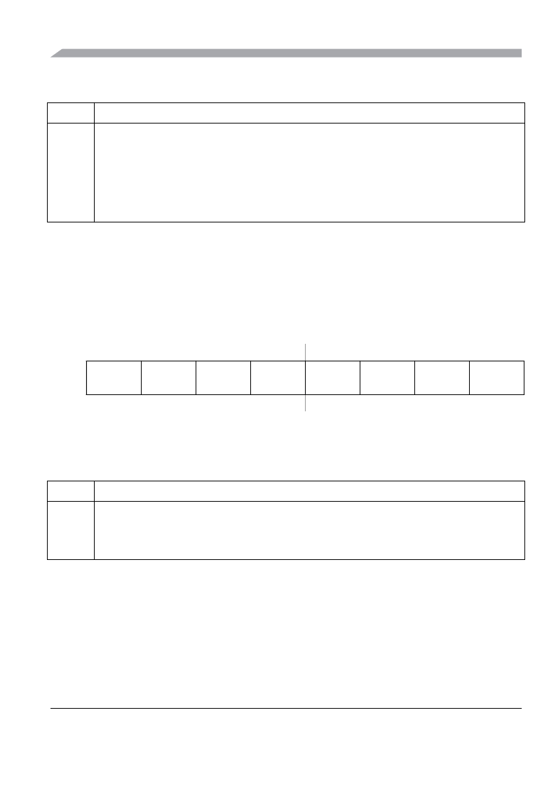
Table 2-97. DDRF Register Field Descriptions
Field
Description
7-0
DDRF
Port F data direction
—
This register controls the data direction of pins 7 through 0.This register configures each Port F pin as either input
or output.
If SPI0 is enabled, the SPI0 determines the pin direction.
Refer to SPI section for details
.
If the associated SCI transmit or receive channel is enabled this register has no effect on the pins. The pin is forced
to be an output if a SCI transmit channel is enabled, it is forced to be an input if the SCI receive channel is enabled.
The data direction bits revert to controlling the I/O direction of a pin when the associated channel is disabled.
1 Associated pin is configured as output.
0 Associated pin is configured as input.
Address 0x037B
Access: User read/write
1
1
Read: Anytime.
Write: Anytime.
7
6
5
4
3
2
1
0
R
RDRF7
RDRF6
RDRF5
RDRF4
RDRF3
RDRF2
RDRF1
RDRF0
W
Reset
0
0
0
0
0
0
0
0
Figure 2-102. Port F Reduced Drive Register (RDRF)
Table 2-98. RDRF Register Field Descriptions
Field
Description
7-0
RDRF
Port F reduced drive
—Select reduced drive for outputs
This register configures the drive strength of output pins 7 through 0 as either full or reduced. If a pin is used as input
this bit has no effect.
1 Reduced drive selected (1/6 of the full drive strength).
0 Full drive strength enabled.
相關(guān)PDF資料 |
PDF描述 |
|---|---|
| PC3S12XEP100J1CVL | Microcontrollers |
| PC3S12XEP100J1CVLR | Microcontrollers |
| PC3S12XEP100J1MAA | Microcontrollers |
| PC3S12XEP100J1MAAR | Microcontrollers |
| PC3S12XEP100J1MAG | Microcontrollers |
相關(guān)代理商/技術(shù)參數(shù) |
參數(shù)描述 |
|---|---|
| PC3S12XEP100J1MAAR | 制造商:FREESCALE 制造商全稱:Freescale Semiconductor, Inc 功能描述:HCS12X Microcontrollers |
| PC3S12XF512J0CLHR | 制造商:FREESCALE 制造商全稱:Freescale Semiconductor, Inc 功能描述:S12X Microcontrollers |
| PC3S12XF512J0CLMR | 制造商:FREESCALE 制造商全稱:Freescale Semiconductor, Inc 功能描述:S12X Microcontrollers |
| PC3S12XF512J0MLHR | 制造商:FREESCALE 制造商全稱:Freescale Semiconductor, Inc 功能描述:S12X Microcontrollers |
| PC3S12XF512J0MLMR | 制造商:FREESCALE 制造商全稱:Freescale Semiconductor, Inc 功能描述:S12X Microcontrollers |
發(fā)布緊急采購(gòu),3分鐘左右您將得到回復(fù)。