- 您現(xiàn)在的位置:買賣IC網(wǎng) > PDF目錄224672 > PALCE22V10H-25JC/4 (LATTICE SEMICONDUCTOR CORP) 24-Pin EE CMOS (Zero Power) Versatile PAL Device PDF資料下載
參數(shù)資料
| 型號(hào): | PALCE22V10H-25JC/4 |
| 廠商: | LATTICE SEMICONDUCTOR CORP |
| 元件分類: | PLD |
| 英文描述: | 24-Pin EE CMOS (Zero Power) Versatile PAL Device |
| 中文描述: | EE PLD, 25 ns, PQCC28 |
| 封裝: | PLASTIC, LCC-28 |
| 文件頁數(shù): | 9/34頁 |
| 文件大?。?/td> | 691K |
| 代理商: | PALCE22V10H-25JC/4 |
第1頁第2頁第3頁第4頁第5頁第6頁第7頁第8頁當(dāng)前第9頁第10頁第11頁第12頁第13頁第14頁第15頁第16頁第17頁第18頁第19頁第20頁第21頁第22頁第23頁第24頁第25頁第26頁第27頁第28頁第29頁第30頁第31頁第32頁第33頁第34頁
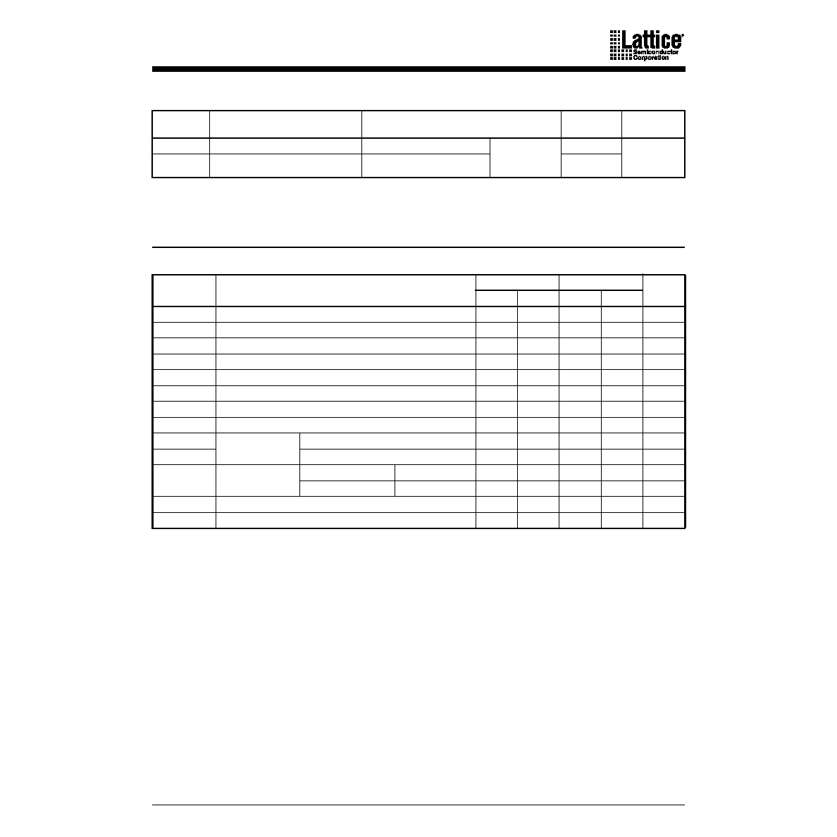
PALCE22V10H-15/25, Q-15/25 (Com’l)
17
CAPACITANCE 1
Note:
1. These parameters are not 100% tested, but are evaluated at initial characterization and at any time the design is modied where
capacitance may be affected.
Notes:
1. See “Switching Test Circuit” for test conditions.
2. These parameters are not 100% tested, but are evaluated at initial characterization and at any time
the design is modied where frequency may be affected.
3. tCF is a calculated value and is not guaranteed. tCF can be found using the following equation:
tCF = 1/fMAX (internal feedback) - tS.
Parameter
Symbol
Parameter Description
Test Conditions
Typ
Unit
CIN
Input Capacitance
VIN = 2.0 V
VCC = 5.0 V
TA = 25°C
f = 1 MHz
5
pF
COUT
Output Capacitance
VOUT = 2.0 V
8
SWITCHING CHARACTERISTICS OVER COMMERCIAL OPERATING RANGES 1
Parameter
Symbol
Parameter Description
-15
-25
Unit
Min
Max
Min
Max
tPD
Input or Feedback to Combinatorial Output
15
25
ns
tS
Setup Time from Input, Feedback or SP to Clock
10
15
ns
tH
Hold Time
0
ns
tCO
Clock to Output
10
15
ns
tAR
Asynchronous Reset to Registered Output
20
25
ns
tARW
Asynchronous Reset Width
15
25
ns
tARR
Asynchronous Reset Recovery Time
10
25
ns
tSPR
Synchronous Preset Recovery Time
10
25
ns
tWL
Clock Width
LOW
8
13
ns
tWH
HIGH
8
13
ns
fMAX
Maximum Frequency
(Note 2)
External Feedback
1/(tS + tCO)
50
33.3
MHz
Internal Feedback (fCNT) 1/(tS + tCF) (Note 3)
58.8
35.7
MHz
tEA
Input to Output Enable Using Product Term Control
15
25
ns
tER
Input to Output Disable Using Product Term Control
15
25
ns
相關(guān)PDF資料 |
PDF描述 |
|---|---|
| PALCE22V10H-5JC/5 | 24-Pin EE CMOS (Zero Power) Versatile PAL Device |
| PALCE22V10H-20JI/4 | 24-Pin EE CMOS (Zero Power) Versatile PAL Device |
| PALCE600 | USE GAL DEVICES FOR NEW DESIGNS |
| PALCE610H-25JC | USE GAL DEVICES FOR NEW DESIGNS |
| PALCE610H-25PC | USE GAL DEVICES FOR NEW DESIGNS |
相關(guān)代理商/技術(shù)參數(shù) |
參數(shù)描述 |
|---|---|
| PALCE22V10H-25JI | 制造商:未知廠家 制造商全稱:未知廠家 功能描述:Electrically-Erasable PLD |
| PALCE22V10H-25JI/4 | 制造商:Rochester Electronics LLC 功能描述:- Bulk |
| PALCE22V10H-25PC | 制造商:未知廠家 制造商全稱:未知廠家 功能描述:Electrically-Erasable PLD |
| PALCE22V10H-25PC/4 | 制造商:Advanced Micro Devices 功能描述: |
| PALCE22V10H-25PI | 制造商:未知廠家 制造商全稱:未知廠家 功能描述:Electrically-Erasable PLD |
發(fā)布緊急采購,3分鐘左右您將得到回復(fù)。