- 您現(xiàn)在的位置:買賣IC網(wǎng) > PDF目錄296762 > PA35 Operational Amplifier PDF資料下載
參數(shù)資料
| 型號: | PA35 |
| 英文描述: | Operational Amplifier |
| 中文描述: | 運(yùn)算放大器 |
| 文件頁數(shù): | 4/4頁 |
| 文件大小: | 69K |
| 代理商: | PA35 |
APEX MICROTECHNOLOGY CORPORATION 5980 NORTH SHANNON ROAD TUCSON, ARIZONA 85741 USA APPLICATIONS HOTLINE: 1 (800) 546-2739
OPERATING
CONSIDERATIONS
PA35
GENERAL
Please read Application Note 1 "General Operating
Considerations" which covers stability, supplies, heat sinking,
mounting, current limit, SOA interpretation, and specication
interpretation. Visit www.apexmicrotech.com for design tools
that help automate tasks such as calculations for stability,
internal power dissipation, current limit and heat sink
selection. The "Application Notes" and "Technical Seminar"
sections contain a wealth of information on specic types of
applications.Package outlines, heat sinks, mounting hardware
and other accessories are located in the "Packages and
Accessories" section. Evaluation Kits are available for most
Apex product models, consult the "Evaluation Kit" section for
details. For the most current version of all Apex product data
sheets, visit www.apexmicrotech.com.
CURRENT LIMIT
Current limit is internal to the amplier, the typical value is
shown in the current limit specication.
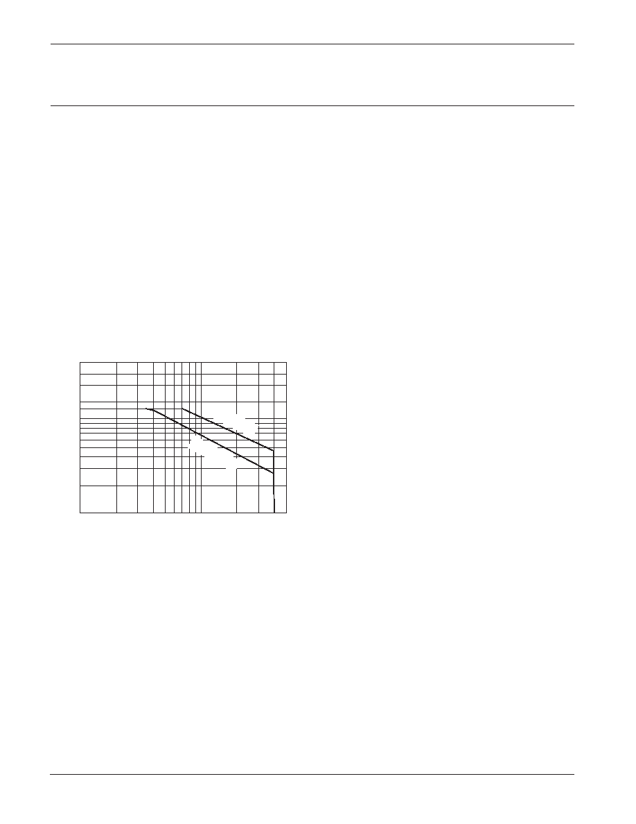
SAFE OPERATING AREA (SOA)
The SOA curves combine the effect of all limits for this
power op amp. For a given application, the direction and
magnitude of the output current should be calculated or
measured and checked against the SOA curves. This is
simple for resistive loads but more complex for reactive and
EMF generating loads. The following guidelines may save
extensive analytical efforts.
Under transient conditions, capacitive and dynamic*
inductive loads up to the following maximum are safe:
±Vs
CAPACITIVE LOAD
INDUCTIVE LOAD
20V
200F
7.5mH
15V
500F
25mH
10V
5mF
35mH
5V
50mF
150mH
* If the inductive load is driven near steady state conditions,
allowing the output voltage to drop more than 6V below the
supply rail while the amplier is current limiting, the inductor
should be capacitively coupled or the supply voltage must be
lowered to meet SOA criteria.
NOTE: For protection against sustained, high energy yback,
external fast-recovery diodes should be used.
MONOLITHIC AMPLIFIER
STABILITY CONSIDERATIONS
All monolithic power op amps use output stage topologies
that present special stability problems. This is primarily due
to non-complementary (both devices are NPN) output
stages with a mismatch in gain and phase response for
different polarities of output current. It is difcult for the
op amp manufacturer to optimize compensation for all
operating conditions.
The recommended R-C network of 1 ohm in series with
0.1F from output to AC common (ground or a supply rail,
with adequate bypass capacitors) will prevent local output
stage oscillations.
The ampliers are internally compensated for unity gain
stability, no additional compensation is required.
THERMAL CONSIDERATIONS
The PA35 may require a thermal washer which is electrically
insulating since the tab is tied to –VS.This can result in thermal
impedances for R θCS of up to 1°C/W or greater.
VBIAS should be set midway between +Vs and -Vs, Vref
is usually ground in dual supply systems or used for level
translation in single supply systems.
MOUNTING PRECAUTIONS
1. Always use a heat sink. Even unloaded, the PA35 can
dissipate up to 3.6 watts. An insulating thermal washer
should always be used.
2. Avoid bending the leads. Such action can lead to internal
damage.
3. Always fasten the tab to the heat sink before the leads are
soldered to xed terminals.
4. Strain relief must be provided if there is any probability of
axial stress to the leads.
4
3
2
1
.1
12
3
4
5
7 8 9
610
20
30
SUPPLY TO OUTPUT DIFFERENTIAL VOLTAGE V –V (V)
SO
OUTPUT
CURRENT
FROM
+V
OR
–V
(A)
SS
40
5
T
= 85
°C
C
DC,
T
= 25°
C
DC,
This data sheet has been carefully checked and is believed to be reliable, however, no responsibility is assumed for possible inaccuracies or omissions. All specications are subject to change without notice.
PA35U REV. A MARCH 2001 2001 Apex Microtechnology Corp.
相關(guān)PDF資料 |
PDF描述 |
|---|---|
| PA37 | Analog IC |
| PA4-5PD11J-D01 | 9 CONTACT(S), MALE, STRAIGHT TWO PART BOARD CONNECTOR, SOLDER, PLUG |
| PA4-5PD11J-P39 | 9 CONTACT(S), MALE, STRAIGHT TWO PART BOARD CONNECTOR, SOLDER, PLUG |
| PA4-5PD11JT-D01 | 9 CONTACT(S), MALE, STRAIGHT TWO PART BOARD CONNECTOR, SOLDER, PLUG |
| PA4-5PD11JT-P39 | 9 CONTACT(S), MALE, STRAIGHT TWO PART BOARD CONNECTOR, SOLDER, PLUG |
相關(guān)代理商/技術(shù)參數(shù) |
參數(shù)描述 |
|---|---|
| PA-35 | 制造商:CENTRALAB 功能描述: 制造商:Electro Switch Corp 功能描述: |
| PA350 | 制造商:未知廠家 制造商全稱:未知廠家 功能描述:RISING CLAMP TERMINAL BLOCK |
| PA351 | 功能描述:按鈕開關(guān) ON-OFF .250 QC TAB RoHS:否 制造商:C&K Components 觸點(diǎn)形式:2 NC - 2 NO 開關(guān)功能:ON ? OFF 電流額定值:4 A 電壓額定值 AC:12 V to 250 V 電壓額定值 DC:12 V to 50 V 功率額定值: 安裝風(fēng)格:Through Hole 照明:Illuminated 照明顏色:None IP 等級:IP 40 端接類型:Solder 觸點(diǎn)電鍍:Silver 執(zhí)行器:Square 蓋顏色: 封裝: 可燃性等級:UL 94 V-0 |
| PA35-13 | 功能描述:ANT PNL TRI 13DBI 3.5GHZ N FEM RoHS:是 類別:RF/IF 和 RFID >> RF 天線 系列:* 標(biāo)準(zhǔn)包裝:1 系列:* |
| PA35135-1 | 制造商:Alpha 3 Manufacturing 功能描述: |
發(fā)布緊急采購,3分鐘左右您將得到回復(fù)。