- 您現(xiàn)在的位置:買賣IC網(wǎng) > PDF目錄369944 > P82C55A (INTEL CORP) CHMOS PROGRAMMABLE PERIPHERAL INTERFACE PDF資料下載
參數(shù)資料
| 型號: | P82C55A |
| 廠商: | INTEL CORP |
| 元件分類: | 微控制器/微處理器 |
| 英文描述: | CHMOS PROGRAMMABLE PERIPHERAL INTERFACE |
| 中文描述: | 24 I/O, PIA-GENERAL PURPOSE, PDIP40 |
| 封裝: | DIP-40 |
| 文件頁數(shù): | 13/23頁 |
| 文件大小: | 325K |
| 代理商: | P82C55A |
82C55A
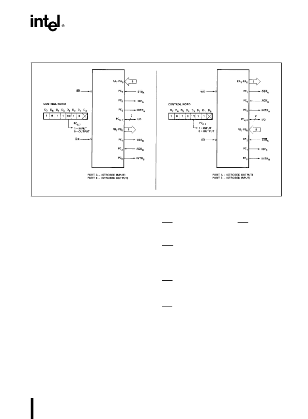
Combinations of MODE 1
Port A and Port B can be individually defined as input or output in Mode 1 to support a wide variety of strobed
I/O applications.
231256–17
Figure 12. Combinations of MODE 1
Operating Modes
MODE 2 (Strobed Bidirectional Bus I/O).
This
functional configuration provides a means for com-
municating with a peripheral device or structure on a
single 8-bit bus for both transmitting and receiving
data (bidirectional bus I/O). ‘‘Handshaking’’ signals
are provided to maintain proper bus flow discipline in
a similar manner to MODE 1. Interrupt generation
and enable/disable functions are also available.
MODE 2 Basic Functional Definitions:
#
Used in Group A
only
.
#
One 8-bit, bi-directional bus port (Port A) and a 5-
bit control port (Port C).
#
Both inputs and outputs are latched.
#
The 5-bit control port (Port C) is used for control
and status for the 8-bit, bi-directional bus port
(Port A).
Bidirectional Bus I/O Control Signal Definition
INTR (Interrupt Request).
A high on this output can
be used to interrupt the CPU for input or output oper-
ations.
Output Operations
OBF (Output Buffer Full).
The OBF output will go
‘‘low’’ to indicate that the CPU has written data out
to port A.
ACK (Acknowledge).
A ‘‘low’’ on this input enables
the tri-state output buffer of Port A to send out the
data. Otherwise, the output buffer will be in the high
impedance state.
INTE 1 (The INTE Flip-Flop Associated with
OBF).
Controlled by bit set/reset of PC
6
.
Input Operations
STB (Strobe Input).
A ‘‘low’’ on this input loads
data into the input latch.
IBF (Input Buffer Full F/F).
A ‘‘high’’ on this output
indicates that data has been loaded into the input
latch.
INTE 2 (The INTE Flip-Flop Associated with IBF).
Controlled by bit set/reset of PC
4
.
13
相關(guān)PDF資料 |
PDF描述 |
|---|---|
| P8344AH | HIGH PERFORMANCE 8 BIT MICROCONTROLLER WITH ON CHIP SERIAL COMMUNICATION CONTROLLER |
| P8044AH | HIGH PERFORMANCE 8 BIT MICROCONTROLLER WITH ON CHIP SERIAL COMMUNICATION CONTROLLER |
| P8744AH | HIGH PERFORMANCE 8 BIT MICROCONTROLLER WITH ON CHIP SERIAL COMMUNICATION CONTROLLER |
| P83C524EFA | CONN, JACK MODULAR 90DEG 4P 4C |
| P83C524EFP | CONN HEADER 12POS SGL PCB 30GOLD |
相關(guān)代理商/技術(shù)參數(shù) |
參數(shù)描述 |
|---|---|
| P82C55A2 | 制造商:Intel 功能描述: |
| P82C55A-2 | 制造商:Rochester Electronics LLC 功能描述: |
| P82C574 | 制造商:未知廠家 制造商全稱:未知廠家 功能描述:Peripheral Interface |
| P82C59A2 | 制造商:INTEL 功能描述:* 制造商:Intel 功能描述: |
| P82C59A-2 | 制造商:Intel 功能描述: |
發(fā)布緊急采購,3分鐘左右您將得到回復(fù)。