- 您現(xiàn)在的位置:買賣IC網(wǎng) > PDF目錄383724 > ort233 (OKI SEMICONDUCTOR CO., LTD.) Reed Switch(舌簧開關(guān)) PDF資料下載
參數(shù)資料
| 型號: | ort233 |
| 廠商: | OKI SEMICONDUCTOR CO., LTD. |
| 英文描述: | Reed Switch(舌簧開關(guān)) |
| 中文描述: | 干簧(舌簧開關(guān)) |
| 文件頁數(shù): | 28/145頁 |
| 文件大小: | 729K |
| 代理商: | ORT233 |
第1頁第2頁第3頁第4頁第5頁第6頁第7頁第8頁第9頁第10頁第11頁第12頁第13頁第14頁第15頁第16頁第17頁第18頁第19頁第20頁第21頁第22頁第23頁第24頁第25頁第26頁第27頁當(dāng)前第28頁第29頁第30頁第31頁第32頁第33頁第34頁第35頁第36頁第37頁第38頁第39頁第40頁第41頁第42頁第43頁第44頁第45頁第46頁第47頁第48頁第49頁第50頁第51頁第52頁第53頁第54頁第55頁第56頁第57頁第58頁第59頁第60頁第61頁第62頁第63頁第64頁第65頁第66頁第67頁第68頁第69頁第70頁第71頁第72頁第73頁第74頁第75頁第76頁第77頁第78頁第79頁第80頁第81頁第82頁第83頁第84頁第85頁第86頁第87頁第88頁第89頁第90頁第91頁第92頁第93頁第94頁第95頁第96頁第97頁第98頁第99頁第100頁第101頁第102頁第103頁第104頁第105頁第106頁第107頁第108頁第109頁第110頁第111頁第112頁第113頁第114頁第115頁第116頁第117頁第118頁第119頁第120頁第121頁第122頁第123頁第124頁第125頁第126頁第127頁第128頁第129頁第130頁第131頁第132頁第133頁第134頁第135頁第136頁第137頁第138頁第139頁第140頁第141頁第142頁第143頁第144頁第145頁
26
REED SWITCH
2-2 Bending the leads
As in the case of cutting the leads, influ-
ence on the pull-in and drop-out charac-
teristics must be checked by actually us-
ing the magnet and the driving method
planned.
2-3 Measuring the electrical characteristics of
reed switches after cutting or bending.
When the leads of a reed switch are cut, it
is not possible to measure electrical char-
acteristics by using a standard test jig.
However, it is possible to measure these
characteristics after processing if a special
jig is made. It is also possible to measure
electrical characteristics of the reed switch
with a bent lead by using the jig similar to
the one used for a reed switch with a cut
lead. However, when both leads are bent,
the reed switch cannot be inserted into a
coil and therefore cannot be measured.
3.
Reed Switch Mounting
Generally, a reed switch is mounted by
soldering or welding. When the mount-
ing space (including its vicinity) is non-
magnetic, there is no influence on opera-
tion but when the material is magnetic,
operation characteristics do change. There-
fore, it is necessary to check these in con-
sideration of the assembling conditions.
3-1 Soldering
Leads are tin plated and are soldered ordi-
narily (250 to 300
°
C). When soldering,
keep the soldering point at least 1 mm
away from the glass end. In addition, there
is also a danger of causing the glass tube to
be damaged by heat if the soldering is
done for a long time. Keep the process to
less than five seconds.
3-2 Welding
When welding, also keep the welding
point at least 1 mm away from the glass
end. When using a large power supply for
welding, heat generated in lead may cause
damage to the glass tube. Precautions to
prevent this are necessary.
Welding current may also induce mag-
netic field and cause the reed switch to
operate. Therefore, it may introduce weld-
ing current to the contact and contact may
be melted. Precautions are also necessary.
3-3 Ultrasonic welding
Be very careful when using ultrasonic
welding methods to weld reed switches
or using ultrasonic welder in the vicinity
of a reed switch.
The ultrasonic can change the contact gap
and the characteristics of the reed switch.
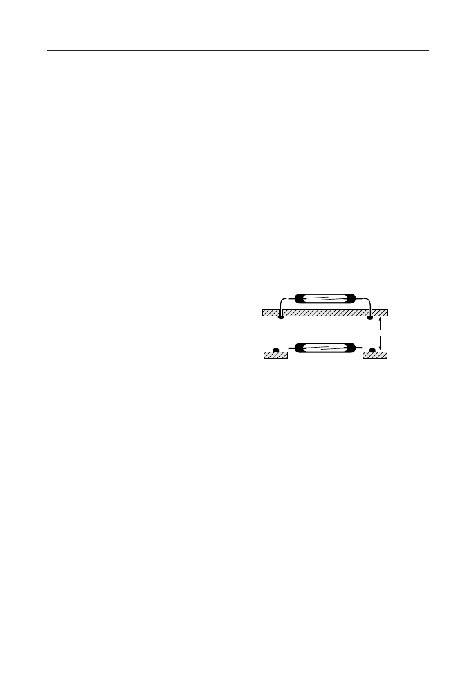
3-4 Mounting on a printed circuit board
When mounting on a printed circuit board,
the reed switch should float on the board
as shown in Figure 3.1 or hole should be
opened in the printed circuit board to
prevent the glass from touching the board
surface. Otherwise, it is possible to cause
a damage to the glass tube because of
physical shocks or other adverse elements
applied externally to it.
4.
Reed Switch Resin Mold
Printed circuit board
Figure 3.1
When reed switches are molded with resin,
it is possible for the resin stress to break or
damage the glass tube. Therefore, the resin
should be selected carefully. Moreover, it
is necessary to perform temperature cycle
testing to ensure selection of safe resin
material.
On the other hand, there is no problem if
silicone or other soft resin is used.
5.
Dropping Reed Switches
Avoid dropping reed switches. If a reed
switch is dropped onto a hard surface
from a height more than 30 cm, it is pos-
sible to cause the characteristics to change.
If a reed switch has been dropped, care-
fully inspect its characteristics and exte-
rior appearance before use.
If a reed switch has been subjected to
shock more than 30 G, the pull-in value
may change.
PRECAUTIONS AND APPLICATIONS
相關(guān)PDF資料 |
PDF描述 |
|---|---|
| ord2212 | Reed Switch(舌簧開關(guān)) |
| ord213 | Reed Switch(舌簧開關(guān)) |
| ord219 | Reed Switch(舌簧開關(guān)) |
| ord234 | Reed Switch(舌簧開關(guān)) |
| ORT82G5 | ORCA ORT82G5 1.0.1-25/2.0-2.5/3.125 Gbits/s Backplane Interface FPSC |
相關(guān)代理商/技術(shù)參數(shù) |
參數(shù)描述 |
|---|---|
| ORT2400 | 制造商:BOT 制造商全稱:Bedford Opto Technology Ltd. 功能描述:4 ELEMENT PCB MOUNT 1.8mm LED ARRAY |
| ORT2400B | 制造商:BOT 制造商全稱:Bedford Opto Technology Ltd. 功能描述:4 ELEMENT PCB MOUNT 1.8mm LED ARRAY |
| ORT2400BL | 制造商:BOT 制造商全稱:Bedford Opto Technology Ltd. 功能描述:4 ELEMENT PCB MOUNT 1.8mm LED ARRAY |
| ORT2400G | 制造商:BOT 制造商全稱:Bedford Opto Technology Ltd. 功能描述:4 ELEMENT PCB MOUNT 1.8mm LED ARRAY |
| ORT2400O | 制造商:BOT 制造商全稱:Bedford Opto Technology Ltd. 功能描述:4 ELEMENT PCB MOUNT 1.8mm LED ARRAY |
發(fā)布緊急采購,3分鐘左右您將得到回復(fù)。