- 您現(xiàn)在的位置:買賣IC網(wǎng) > PDF目錄382355 > MX623 (Electronic Theatre Controls, Inc.) Line-Powered Call Progress Tone Detector PDF資料下載
參數(shù)資料
| 型號: | MX623 |
| 廠商: | Electronic Theatre Controls, Inc. |
| 英文描述: | Line-Powered Call Progress Tone Detector |
| 中文描述: | 線路供電呼叫過程音檢測 |
| 文件頁數(shù): | 3/6頁 |
| 文件大小: | 59K |
| 代理商: | MX623 |

1997 MX
COM Inc.
4800 Bethania Station Road, Winston-Salem, NC 27105-1201 USA All trademarks and service marks are held by their respective companies.
www.mxcom.com Tele: 800 638-5577 910 744-5050 Fax: 910 744-5054
Doc. # 20480091.003
Line- Powered Call Progress Detector
3
MX623 Preliminary Information
Application Information
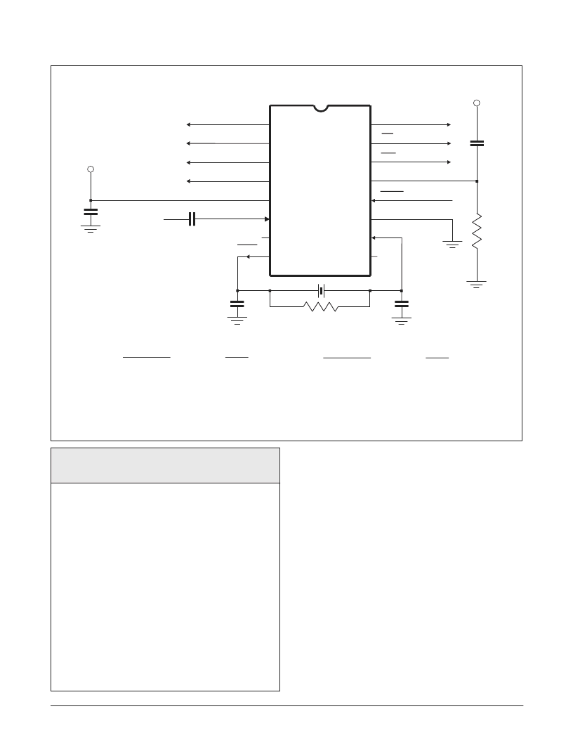
Figure 2 - Recommended External Components
Band Edges (Hz)
Lower
Edge
Nominal
Center
Freq.
Hex
Output Code
Upper
Edge
Character Q3 Q2 Q1 Q0
0
1
2
3
4
5
6
7
8
9
A
B
C
D
E
F
0
0
0
0
0
0
0
0
1
1
1
1
1
1
1
1
0
0
0
0
1
1
1
1
0
0
0
0
1
1
1
1
0
0
1
1
0
0
1
1
0
0
1
1
0
0
1
1
0
1
0
1
0
1
0
1
0
1
0
1
0
1
0
1
364
488
520
580
386
412
436
463
900
1273
1350
1750
2062
386
520
580
618
412
436
463
487
1008
1325
1455
1855
2140
375
500
550
600
400
425
450
475
950
1300
1400
1800
2100
frequency not guaranteed
frequency not guaranteed
N
OTONE
Table 1 - Tone Decode Frequencies
Timing Information
With CS Low - Figure 3
After initial power-up and the Hold input inactive (High),
as frequencies are input, with the Data Change output
as an active (High) indicator, the data is presented at
the Data Outputs.
If/when the Hold input is placed active (Low), the data
at the Data Outputs is frozen and the Data Change
output held High at its next active excursion -until the
Hold input is returned High.
With the Hold input held High - Figure 4
As frequencies are input a correct decode will produce
an active (Low) interrupt level.
This interrupt (IRQ) is serviced and reset by an active
(Low) CS input.
Note the ‘valid data’ period at the Data Outputs.
Component
R
1
R
2
C
1
C
2
Value
1.0M
1.0M
.047
μ
F
.0047
μ
F
Component
C
3
C
4
C
5
X
1
Value
33.0pF
33.0pF
1.0
μ
F
3.579545MHz
Tolerances R = ±10%, C = ±20%
V
DD
V
DD
V
DD
C
1
R
1
C
4
X
1
R
2
C
3
C
2
V
SS
1
2
3
4
5
6
7
8
16
15
14
13
12
11
10
9
XTAL/CLOCK
P U R S
DATA CHANGE
SIGNAL IN
COMPOSITE SIGNAL IN
A HEX Code
Output representing
the decoded tone
frequency --
See Table 1
DATA OUTPUTS
Q3
Q0
Q1
Q2
C
5
XTAL
HOLD
IRQ
CS
MX623P
相關(guān)PDF資料 |
PDF描述 |
|---|---|
| MX803A | Audio Signaling Processor |
| MX812 | VSR CODEC WITH DRAM CONTROL |
| MX812DW | VSR CODEC WITH DRAM CONTROL |
| MX812J | VSR CODEC WITH DRAM CONTROL |
| MX841 | White LED Step-Up Converter |
相關(guān)代理商/技術(shù)參數(shù) |
參數(shù)描述 |
|---|---|
| MX623P | 制造商:未知廠家 制造商全稱:未知廠家 功能描述:Subscriber Line Metering/Monitoring Circuit |
| MX629 | 制造商:CMLMICRO 制造商全稱:CML Microcircuits 功能描述:DELTA MODULATION CODEC meets Mil-Std-188-113 |
| MX629J | 制造商:CMLMICRO 制造商全稱:CML Microcircuits 功能描述:DELTA MODULATION CODEC meets Mil-Std-188-113 |
| MX629LH | 制造商:CML Innovative Technologies 功能描述:Military Delta Modulation Codec, Tube |
| MX629M | 制造商:未知廠家 制造商全稱:未知廠家 功能描述:RF Modulator/Demodulator |
發(fā)布緊急采購,3分鐘左右您將得到回復(fù)。