- 您現(xiàn)在的位置:買(mǎi)賣(mài)IC網(wǎng) > PDF目錄359240 > MV5089 (Zarlink Semiconductor Inc.) DTMF GENERATOR PDF資料下載
參數(shù)資料
| 型號(hào): | MV5089 |
| 廠商: | Zarlink Semiconductor Inc. |
| 英文描述: | DTMF GENERATOR |
| 中文描述: | 雙音多頻發(fā)生器 |
| 文件頁(yè)數(shù): | 4/7頁(yè) |
| 文件大?。?/td> | 91K |
| 代理商: | MV5089 |
MV5089
3
PIN FUNCTIONS
PIN
NAME
DESCRIPTION
1
V
DD
Positive Power Supply
2
TONE
DISABLE
This input has an internal pull-up resistor to V
D
D. When connected to V
SS
no
tones are generated by ant key depression allowing the keyboard to be used for
purposes other than DTMF signalling.
3,4,5,9
Column 1-4
These CMOS inputs are held at V
SS
by an internal pull-up resistor and are activated
by the application of V
SS
.
6
V
SS
Negative Power Supply (OV)
7,8
OSC In,
OSC Out
On-chip inverter completes the oscillator when a 3,579545 MHz crystal is
connected to these pins. OSC In is the inverter input and OSC Out is the output.
10
Any Key Down This is an NMOS transistor output which switches to VSS while any key is
depressed. Otherwise this output is high impedance. Switching is independent of
Tone Disable and Single Tone Inhibit.
11,12,13,14
Row 1-4
As
Column 1-4
inputs.
15
Single Tone
Inhibit
This input has a pull-up resistor to V
SS
. When left unconnected or tied to V
SS
,
dual tones may be generated, but keyboard input combinations resulting
in single tone generation are inhibited. When VDD is applied single or
dual tones may be generated.
16
Tone Out
Emitter output of a bipolar NPN transistor whose collector is tied to V
DD
. Input to
this transistor is from an op-amp which mixes the row and column tones.
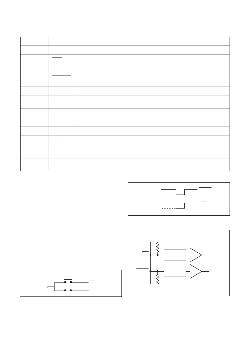
Figure 6: Row and Column inputs
Figure 4: 2 of 8 DTMF keyboard
ROW AND COLUMN INPUTS
These inputs are compatible with the standard 2-of-8
keyboard or with an electronic input. Figures 4 and 5 show
these input configurations and Fig.6 shows the internal chip
structure of these inputs.
When operating with a keyboard, dual tones are generated
when any single button is pushed.
With Single Tone Inhibit at V
DD
, connection of V
SS
to a
single column causes the generation of that Column tone.
Connection of V
SS
to more than one Column will result in no
Column tones being generated. Connection of V
SS
to Rows
only generates no tone - a Column must be connected to V
SS
.
A single Row tone only may be generated by connecting 2
columns, and the desired row, to V
SS
.
OUTPUT TONE LEVEL
The output tone level of the MV5089 is proportional to the
applied DC supply voltage.
A regulated supply will normally be used which may be
designed to provide stability over the temperature range.
ROW
COL
V
SS
Figure 5: Electronic input
STATIC
PROTECTION
STATIC
PROTECTION
Row input
sensing circuit
Column input
sensing circuit
ROW
INPUT
COLUMN
INPUT
V
DD
V
DD
R
C
R
R
COLUMN
ROW
V
DD
V
SS
V
DD
V
SS
相關(guān)PDF資料 |
PDF描述 |
|---|---|
| MV5290 | Current Limiter Diode |
| MV5291 | Current Limiter Diode |
| MV5292 | Current Limiter Diode |
| MV5293 | Current Limiter Diode |
| MV5294 | Current Limiter Diode |
相關(guān)代理商/技術(shù)參數(shù) |
參數(shù)描述 |
|---|---|
| MV5089-DP | 制造商:未知廠家 制造商全稱(chēng):未知廠家 功能描述:Telecommunication IC |
| MV5089MP | 制造商:未知廠家 制造商全稱(chēng):未知廠家 功能描述:Tone Telephone Dialer |
| MV5089-MP | 制造商:未知廠家 制造商全稱(chēng):未知廠家 功能描述:Telecommunication IC |
| MV5094A | 功能描述:標(biāo)準(zhǔn)LED-通孔 Hi Eff Red Diffused Bipolar RoHS:否 制造商:Vishay Semiconductors 照明顏色:Red 光強(qiáng)度:0.7 mcd 波長(zhǎng)/色溫:615 nm 顯示角:45 deg 透鏡顏色/類(lèi)型:Clear, Non-Diffused 正向電流:70 mA 正向電壓:1.83 V to 3.03 V LED 大小:2 mm 系列: 封裝:Tube |
| MV5094A | 制造商:Fairchild Semiconductor Corporation 功能描述:LED LAMP ROHS COMPLIANT:NO |
發(fā)布緊急采購(gòu),3分鐘左右您將得到回復(fù)。