- 您現(xiàn)在的位置:買賣IC網(wǎng) > PDF目錄385641 > MUR1620CTR (ON SEMICONDUCTOR) SWITCHMODE Power Rectifier(開關(guān)模式功率整流管) PDF資料下載
參數(shù)資料
| 型號: | MUR1620CTR |
| 廠商: | ON SEMICONDUCTOR |
| 元件分類: | 參考電壓二極管 |
| 英文描述: | SWITCHMODE Power Rectifier(開關(guān)模式功率整流管) |
| 中文描述: | 8 A, 200 V, SILICON, RECTIFIER DIODE, TO-220AB |
| 封裝: | PLASTIC, CASE 221A-09, 3 PIN |
| 文件頁數(shù): | 1/6頁 |
| 文件大小: | 62K |
| 代理商: | MUR1620CTR |
Semiconductor Components Industries, LLC, 2005
September, 2005 Rev. 3
1
Publication Order Number:
MUR1620CTR/D
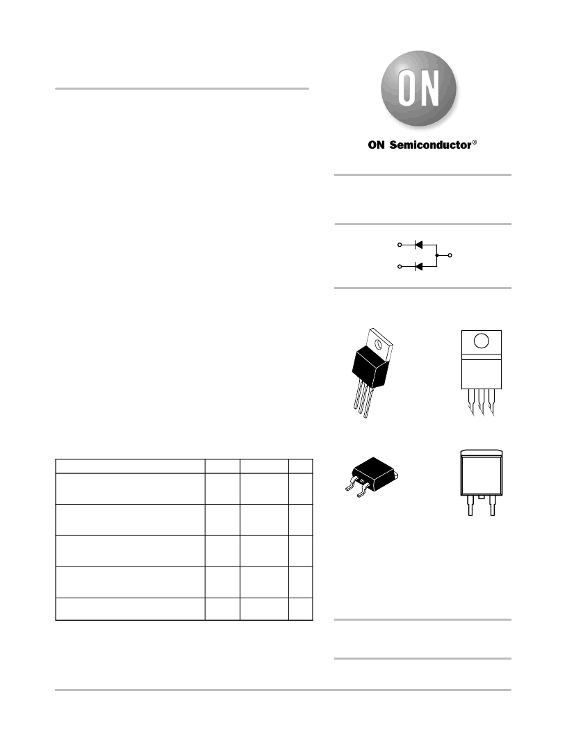
MUR1620CTR,
MURB1620CTR
Preferred Device
SWITCHMODE
Power Rectifier
These stateoftheart devices are designed for use in negative
switching power supplies, inverters and as free wheeling diodes. Also,
used in conjunction with common cathode dual Ultrafast Rectifiers,
makes a single phase fullwave bridge.
Features
Common Anode Dual Rectifier (8.0 A per Leg or 16 A per Package)
Ultrafast 35 Nanosecond Reverse Recovery Times
Exhibits Soft Recovery Characteristics
High Temperature Glass Passivated Junction
Low Leakage Specified @ 150
°
C Case Temperature
Current Derating @ Both Case and Ambient Temperatures
Epoxy Meets UL 94 V0 @ 0.125 in
Complement to MUR1620CT and MURB1620CT Common Cathode
Device
PbFree Packages are Available
Mechanical Characteristics:
Case: Epoxy, Molded
Weight: MUR1620CTR: 1.9 Grams (Approximately)
MURB1620CTR: 1.7 Grams (Approximately)
Finish: All External Surfaces Corrosion Resistant and Terminal
Leads are Readily Solderable
Lead Temperature for Soldering Purposes:
260
°
C Max. for 10 Seconds
MAXIMUM RATINGS
(Per Leg)
Rating
Symbol
Value
Unit
Peak Repetitive Reverse Voltage
Working Peak Reverse Voltage
DC Blocking Voltage
V
RRM
V
RWM
V
R
200
V
Average Rectified Forward Voltage
(Rated V
R
, T
C
= 160
°
C)
Per Leg
Per Total Device
I
F(AV)
8.0
16
A
Peak Repetitive Surge Current
(Rated V
R
, Square Wave,
20 kHz, T
C
= 140
°
C)
Per Diode
I
FM
16
A
NonRepetitive Peak Surge Current
(Surge Applied at Rated Load Conditions
Halfwave, Single Phase, 60 Hz)
I
FSM
100
A
Operating Junction and Storage
Temperature Range
T
J
, T
stg
65 to +175
°
C
Maximum ratings are those values beyond which device damage can occur.
Maximum ratings applied to the device are individual stress limit values (not
normal operating conditions) and are not valid simultaneously. If these limits are
exceeded, device functional operation is not implied, damage may occur and
reliability may be affected.
ULTRAFAST RECTIFIER
16 AMPERES, 200 VOLTS
1
3
2, 4
Preferred
devices are recommended choices for future use
and best overall value.
http://onsemi.com
D
2
PAK
CASE 418B
STYLE 5
3
4
1
MARKING
DIAGRAMS
U1620R = Device Code
KAK
= Diode Polarity
A
= Assembly Location
Y
= Year
WW
= Work Week
G
= PbFree Package
AYWW
U1620RG
KAK
See detailed ordering and shipping information in the package
dimensions section on page 4 of this data sheet.
ORDERING INFORMATION
TO220AB
CASE 221A
STYLE 7
AYWW
U1620RG
KAK
相關(guān)PDF資料 |
PDF描述 |
|---|---|
| MURB1620CTR | SWITCHMODE Power Rectifier(開關(guān)模式功率整流管) |
| MUR1620CT | SWITCHMODE Power Rectifier(開關(guān)方式電源整流器) |
| MUR2100E | SWITCHMODE Power Rectifier(開關(guān)模式功率整流管) |
| MUR3020PT | SWITCHMODE Power Rectifiers(開關(guān)模式功率整流管) |
| MUR3060PT | SWITCHMODE Power Rectifiers(開關(guān)模式功率整流器) |
相關(guān)代理商/技術(shù)參數(shù) |
參數(shù)描述 |
|---|---|
| MUR1620CTR/D | 制造商:未知廠家 制造商全稱:未知廠家 功能描述:SWITCHMODE? Dual Ultrafast Power Rectifier |
| MUR1620CTR_05 | 制造商:ONSEMI 制造商全稱:ON Semiconductor 功能描述:ULTRAFAST RECTIFIER 16 AMPERES, 200 VOLTS |
| MUR1620CTRG | 功能描述:整流器 200V 16A UltraFast RoHS:否 制造商:Vishay Semiconductors 產(chǎn)品:Standard Recovery Rectifiers 配置: 反向電壓:100 V 正向電壓下降: 恢復(fù)時間:1.2 us 正向連續(xù)電流:2 A 最大浪涌電流:35 A 反向電流 IR:5 uA 安裝風格:SMD/SMT 封裝 / 箱體:DO-221AC 封裝:Reel |
| MUR1620CTRG | 制造商:ON Semiconductor 功能描述:Fast Recovery Power Rectifier |
| MUR1620FC | 制造商:LUGUANG 制造商全稱:Shenzhen Luguang Electronic Technology Co., Ltd 功能描述:Ultra Fast Rectifiers |
發(fā)布緊急采購,3分鐘左右您將得到回復(fù)。