- 您現(xiàn)在的位置:買賣IC網(wǎng) > PDF目錄382352 > MTV030 (Electronic Theatre Controls, Inc.) On-Screen Display with Auto-Sizing Controller PDF資料下載
參數(shù)資料
| 型號(hào): | MTV030 |
| 廠商: | Electronic Theatre Controls, Inc. |
| 英文描述: | On-Screen Display with Auto-Sizing Controller |
| 中文描述: | 屏幕顯示與自動(dòng)上漿控制器 |
| 文件頁(yè)數(shù): | 15/21頁(yè) |
| 文件大?。?/td> | 372K |
| 代理商: | MTV030 |
第1頁(yè)第2頁(yè)第3頁(yè)第4頁(yè)第5頁(yè)第6頁(yè)第7頁(yè)第8頁(yè)第9頁(yè)第10頁(yè)第11頁(yè)第12頁(yè)第13頁(yè)第14頁(yè)當(dāng)前第15頁(yè)第16頁(yè)第17頁(yè)第18頁(yè)第19頁(yè)第20頁(yè)第21頁(yè)

15/21
MTV030 Revision 1.0 10/15/1999
MTV030
MYSON
TECHNOLOGY
Column 28 ~ column 31
: Reserved.
Notes : The register located at column 31 of row 15 are reserved for the testing. Don’t program this
byte anytime in normal operation.
ROW 16
R1, G1, B1 - Define the shadow color of window 1. The initial value is (0, 0, 0) after power up.
R2, G2, B2 - Define the shadow color of window 2. The initial value is (0, 0, 0) after power up.
R3, G3, B3 - Define the shadow color of window 3. The initial value is (0, 0, 0) after power up.
R4, G4, B4 - Define the shadow color of window 4. The initial value is (0, 0, 0) after power up.
Column 2 ~ column 31
: Reserved.
3.13 Auto sizing video measurement
The auto sizing video measurement module monitors horizontal and vertical flyback pulses and their relation-
ship to video content. In horizontal measurement, the HFLB is the reference signal. As PLL clock is the certain
multiple of HFLB frequency, the measurements for HFLB and R,G,BIN are all based on the PLL clock. In ver-
tical measurement, the VFLB pulse is reference signal and the HFLB is the counting clock. HFLB and VFLB
have an exact timing relationship to the active raster display on the monitor. When the HFLB, VFLB sync sig-
nals and the R,G,BIN video signals (taken from the output of pre-amplifier) are compared, it will feedback to
MCU a lot of information about the display size and centering. If back porch is much smaller than front porth,
then the video information is too much to the left (or up in the vertical direction). If both front porth and back
porth percentage of the total display period is too large, then the display size is too small. MCU can change
the display size and center until front and back porthes are equal and the porthes to active video ratio is cor-
rect. Please note that due to the deviation of analog circuits, building a ratio table of correct porches to video
for different operating frequencies is needed. And it is recommend that video contrast is set to maximum first
for the correct capture of video information.
Column 0
B7
-
b6
R1
b5
G1
b4
B1
b3
-
b2
R2
b1
G2
b0
B2
Column 1
B7
-
b6
R3
b5
G3
b4
B3
b3
-
b2
R4
b1
G4
b0
B4
255
0
1
2
3
255
0
1
2
3
m
m+1
PWMCK
PWM0
PWM1
PWM2
PWM3
PWM4
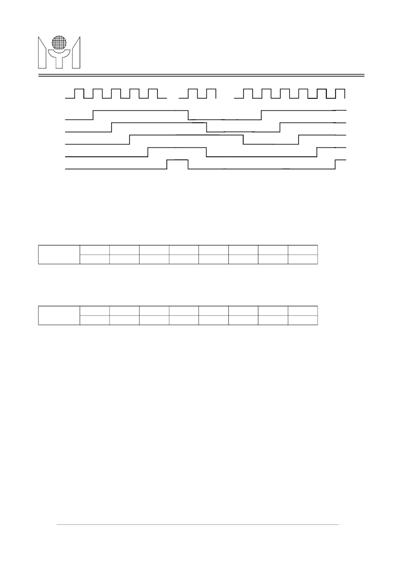
FIGURE 9. 5 Channel PWM Output Rising Edges Are Separated by One PWMCK
4
相關(guān)PDF資料 |
PDF描述 |
|---|---|
| MTV112M | 8051 Embedded CRT Monitor Controller Flash Version |
| MTV118 | On-Screen-Display for LCD Monitor |
| MTV121 | Super On-Screen-Display for LCD Monitor |
| MUA08A | 265mW at 3.3V Supply Audio Power Amplifier with Shutdown Mode |
| MUB08A | 1W, Bypass-Capacitor-less Audio Amplifier with Internal Selectable Gain |
相關(guān)代理商/技術(shù)參數(shù) |
參數(shù)描述 |
|---|---|
| MTV038 | 制造商:未知廠家 制造商全稱:未知廠家 功能描述:On-Screen Display Controller for CRT/LCD Monitor |
| MTV038N | 制造商:未知廠家 制造商全稱:未知廠家 功能描述:On-Screen Display Controller for CRT/LCD Monitor |
| MTV038N20 | 制造商:未知廠家 制造商全稱:未知廠家 功能描述:On-Screen Display Controller for CRT/LCD Monitor |
| MTV048 | 制造商:未知廠家 制造商全稱:未知廠家 功能描述:On-Screen-Display Controller for CRT/LCD Monitor |
| MTV-10-250L | 制造商:3M Electronic Products Division 功能描述:Highland(TM) Vinyl Insulated Male Tab MTV10-250L, 12-10 AWG |
發(fā)布緊急采購(gòu),3分鐘左右您將得到回復(fù)。