- 您現(xiàn)在的位置:買賣IC網(wǎng) > PDF目錄383643 > MT8977AC (Mitel Networks Corporation) Ultraframer DS3/E3/DS2/E2/DS1/E1/DS0 PDF資料下載
參數(shù)資料
| 型號: | MT8977AC |
| 廠商: | Mitel Networks Corporation |
| 元件分類: | 通信及網(wǎng)絡(luò) |
| 英文描述: | Ultraframer DS3/E3/DS2/E2/DS1/E1/DS0 |
| 中文描述: | Ultraframer DS3/E3/DS2/E2/DS1/E1/DS0 |
| 文件頁數(shù): | 12/26頁 |
| 文件大小: | 344K |
| 代理商: | MT8977AC |
MT8977
ISO-CMOS
Preliminary Information
4-110
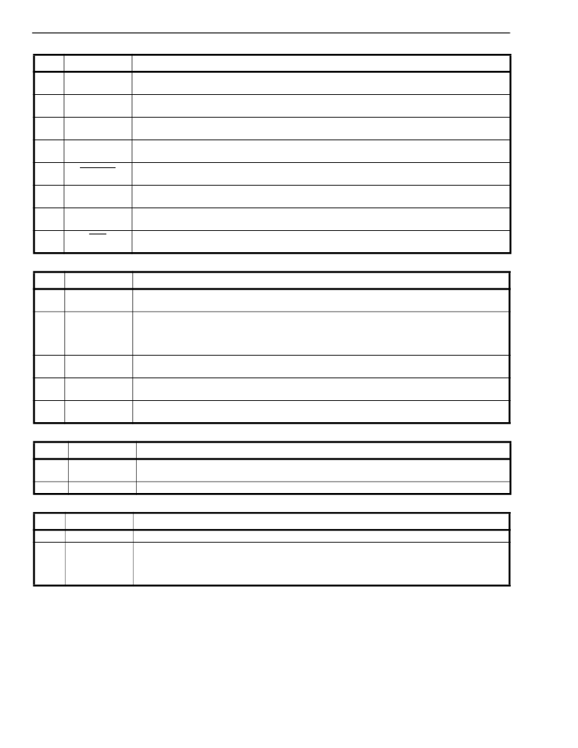
Table 8. Master Status Word 1 (Channel 15, CSTo)
Table 9. Master Status Word 2 (Channel 31, CSTo)
Table 10. Phase Status Word (Channel 3, CSTo)
Table 11. Per Channel Status Word Output on CSTo
Bit
Name
Description
7
YLALR
Yellow Alarm Indication.
This bit is set when the chip is receiving a 0 in bit position 2 of every
DS0 channel.
This bit is set if the frame search algorithm found more than one possible frame candidate when it
went into frame synchronization.
Terminal Framing Bit Error.
The state of this bit changes every time the chip detects 4 errors in
the F
T
or FPS bit pattern. The bit will not change state more than once every 96ms.
ESF Yellow Alarm.
This bit is set when the device has observed a sequence of eight one’s and
eight 0’s in the FDL bit positions.
Multiframe Synchronization.
This bit is cleared when D3/D4 multiframe synchronization has
been achieved. Applicable only in D3/D4 and SLC-96 modes.
Bipolar Violation Count.
The state of this bit changes every time the device counts 256 bipolar
violations.
Slip Indication.
This bit changes state every time the elastic buffer in the device performs a
controlled slip.
Synchronization.
This bit is set when the device has not achieved synchronization. The bit is
clear when the device has synchronized to the received DS1 data stream.
6
MIMIC
5
ERR
4
ESFYLW
3
MFSYNC
2
BPV
1
SLIP
0
SYN
Bit
7
Name
BlAlm
Description
Blue Alarm.
This bit is set if the receiver has detected two frames of 1’s and an out of frame
condition. It is reset by any 250 microsecond interval that contains a zero.
Frame Count.
This is the ninth and most significant bit of the “Phase Status Word“ (see Table
10). If the phase status word is incrementing, this bit will toggle when the phase reading exceeds
channel 31, bit 7. If the phase word is decrementing, then this bit will toggle when the reading
goes below channel 0, bit 0.
External Status.
This bit reflects the state of the external status pin (XSt). The state of the XSt
pin is sampled once per frame.
Bipolar Violation Count.
These two bits change state every 128 and every 64 bipolar violations,
respectively.
CRC Error Count.
These three bits count received CRC errors. The counter will reset to zero
when it reaches terminal count. Valid only in ESF mode.
6
FrCnt
5
XSt
4-3
BPVCnt
2-0
CRCCNT
Bit
7-3
Name
ChannelCnt
Description
Channel Count.
These five bits indicate the ST-BUS channel count between the ST-BUS frame
pulse and the rising edge of E8Ko.
Bit Count.
These three bits provide one bit resolution within the channel count described above.
2-0
BitCnt
Bit
Name
Description
7-4
3
2
1
0
Unused
A
B
C
D
Unused Bits.
Will be output as 0’s.
These are the 4 signalling bits as extracted from the received DS1 bit stream.
The bits are debounced for 6 to 9 ms if the debounce feature is enabled via bit 7 in Master Control
Word 1.
The elastic buffer in the MT8977 permits the device
to handle 26 ST-BUS channels or 156 UI of jitter/
wander (see description of elastic buffer in the next
section). In order to prevent slips from occurring, the
frequency corrections would have to be implemented
such that the deviation in the phase status word is
limited to 26 channels peak-to-peak. It is possible to
use a more sophisticated protocol, which would
center
the
elastic
buffer
and
permit
more
jitter/wander to be handled. However, for most
applications, including ACCUNET
T1.5 (138 UI),
the 156 UI of jitter/wander tolerance is acceptable.
相關(guān)PDF資料 |
PDF描述 |
|---|---|
| MT8977AE | Ultraframer DS3/E3/DS2/E2/DS1/E1/DS0 |
| MT8977AP | Ultraframer DS3/E3/DS2/E2/DS1/E1/DS0 |
| MT8979 | Ultraframer DS3/E3/DS2/E2/DS1/E1/DS0 |
| MT8979 | Ultraframer DS3/E3/DS2/E2/DS1/E1/DS0 |
| MT8979AE | Ultraframer DS3/E3/DS2/E2/DS1/E1/DS0 |
相關(guān)代理商/技術(shù)參數(shù) |
參數(shù)描述 |
|---|---|
| MT8977AE | 制造商:MITEL 制造商全稱:Mitel Networks Corporation 功能描述:ISO-CMOS ST-BUS⑩ FAMILY T1/ESF Framer Circuit |
| MT8977AP | 制造商:Rochester Electronics LLC 功能描述: 制造商:Mitel Networks Corporation 功能描述: 制造商:Zarlink Semiconductor Inc 功能描述: 制造商:ZARLINK 功能描述: |
| MT8977APR | 制造商:Rochester Electronics LLC 功能描述: 制造商:Zarlink Semiconductor Inc 功能描述: 制造商:ZARLINK 功能描述: |
| MT8979 | 制造商:MITEL 制造商全稱:Mitel Networks Corporation 功能描述:ISO-CMOS ST-BUS⑩ FAMILY CEPT PCM 30/CRC-4 Framer & Interface |
| MT8979AC | 制造商:MITEL 制造商全稱:Mitel Networks Corporation 功能描述:ISO-CMOS ST-BUS⑩ FAMILY CEPT PCM 30/CRC-4 Framer & Interface |
發(fā)布緊急采購,3分鐘左右您將得到回復(fù)。