- 您現(xiàn)在的位置:買賣IC網(wǎng) > PDF目錄45387 > MSC1211Y5PAGTG4 (TEXAS INSTRUMENTS INC) 8-BIT, FLASH, 40 MHz, MICROCONTROLLER, PQFP64 PDF資料下載
參數(shù)資料
| 型號: | MSC1211Y5PAGTG4 |
| 廠商: | TEXAS INSTRUMENTS INC |
| 元件分類: | 微控制器/微處理器 |
| 英文描述: | 8-BIT, FLASH, 40 MHz, MICROCONTROLLER, PQFP64 |
| 封裝: | GREEN, PLASTIC, TQFP-64 |
| 文件頁數(shù): | 47/111頁 |
| 文件大小: | 1102K |
| 代理商: | MSC1211Y5PAGTG4 |
第1頁第2頁第3頁第4頁第5頁第6頁第7頁第8頁第9頁第10頁第11頁第12頁第13頁第14頁第15頁第16頁第17頁第18頁第19頁第20頁第21頁第22頁第23頁第24頁第25頁第26頁第27頁第28頁第29頁第30頁第31頁第32頁第33頁第34頁第35頁第36頁第37頁第38頁第39頁第40頁第41頁第42頁第43頁第44頁第45頁第46頁當前第47頁第48頁第49頁第50頁第51頁第52頁第53頁第54頁第55頁第56頁第57頁第58頁第59頁第60頁第61頁第62頁第63頁第64頁第65頁第66頁第67頁第68頁第69頁第70頁第71頁第72頁第73頁第74頁第75頁第76頁第77頁第78頁第79頁第80頁第81頁第82頁第83頁第84頁第85頁第86頁第87頁第88頁第89頁第90頁第91頁第92頁第93頁第94頁第95頁第96頁第97頁第98頁第99頁第100頁第101頁第102頁第103頁第104頁第105頁第106頁第107頁第108頁第109頁第110頁第111頁
MSC1211, MSC1212
MSC1213,MSC1214
SBAS323G JUNE 2004 REVISED OCTOBER 2007
www.ti.com
40
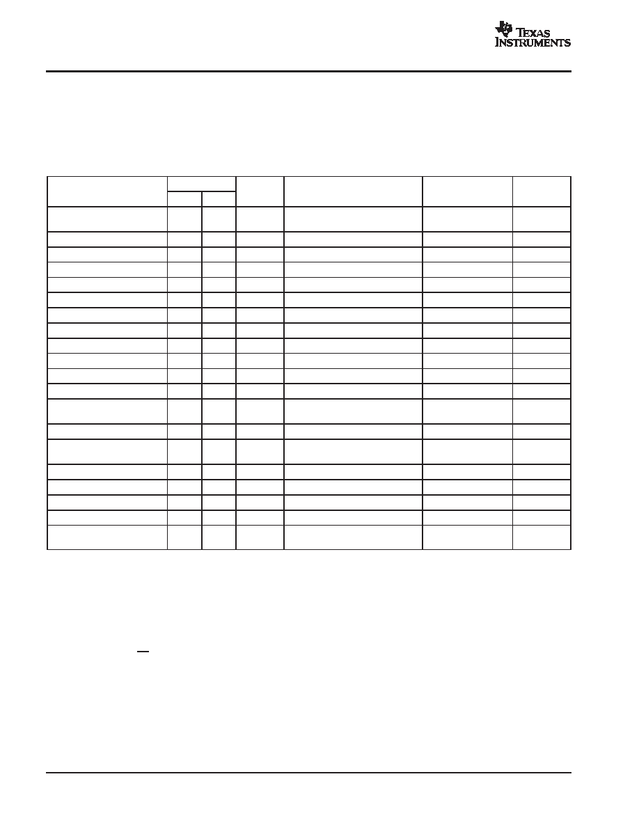
INTERRUPTS
The MSC1211/12/13/14 use a three-priority interrupt
system. As shown in Table 8, each interrupt source has an
independent priority bit, flag, interrupt vector, and enable
(except that nine interrupts share the Auxiliary Interrupt
(AI) at the highest priority). In addition, interrupts can be
globally enabled or disabled. The interrupt structure is
compatible with the original 8051 family. All of the standard
interrupts are available.
Table 8. Interrupt Summary
INTERRUPT
PRIORITY
INTERRUPT/EVENT
ADDR
NUM
PRIORITY
FLAG
ENABLE
PRIORITY
CONTROL
DVDD Low Voltage/HW Break-
point
33h
6
High
EDLVB (AIE.0 or AIPOL.0)(1)(2)
EBP (BPCON.7)(1)
EDLVB (AIE.0)(1)
EBP (BPCON.0)(1)
N/A
AVDD Low Voltage
33h
6
0
EALV (AIE.1 or AIPOL.1)(1)(2)
EALV (AIE.1)(1)
N/A
SPI Receive / I2C(3)
33h
6
0
ESPIR/EI2C (AIE.2 or AIPOL.2)(1)(2)
ESPIR/EI2C (AIE.2)(1)
N/A
SPI Transmit
33h
6
0
ESPIT (AIE.3 or AIPOL.3)(1)(2)
ESPIT (AIE.3)(1)
N/A
Milliseconds Timer
33h
6
0
EMSEC (AIE.4 or AIPOL.4)(1)(2)
EMSEC (AIE.4)(1)
N/A
ADC
33h
6
0
EADC (AIE.5 or AIPOL.5)(1)(2)
EADC (AIE.5)(1)
N/A
Summation Register
33h
6
0
ESUM (AIE.6 or AIPOL.6)(1)(2)
ESUM (AIE.6)(1)
N/A
Seconds Timer
33h
6
0
ESEC (AIE.7 or AIPOL.7)(1)(2)
ESEC (AIE.7)(1)
N/A
External Interrupt 0
03h
0
1
IE0 (TCON.1)(4)
EX0 (IE.0)(6)
PX0 (IP.0)
Timer 0 Overflow
0Bh
1
2
TF0 (TCON.5)(5)
ET1 (IE.1)(6)
PT0 (IP.1)
External Interrupt 1
13h
2
3
IE1 (TCON.3)(4)
EX1 (IE.2)(6)
PX1 (IP.2)
Timer 1 Overflow
0Bh
3
4
TF1 (TCON.7)(5)
ET1 (IE.3)(6)
PT1 (IP.3)
Serial Port 0
23h
4
5
RI_0 (SCON0.0)
TI_0 (SCON0.1)
ES0 (IE.4)(6)
PS0 (IP.4)
Timer 2 Overflow
2Bh
5
6
TF2 (T2CON.7)
ET2 (IE.5)(6)
PT2 (IP.5)
Serial Port 1
3Bh
7
RI_1 (SCON1.0)
TI_1 (SCON1.1)
ES1 (IE.6)(6)
PS1 (IP.6)
External Interrupt 2
43h
8
IE2 (EXIF.4)(4)
EX2 (EIE.0)(6)
PX2 (EIP.0)
External Interrupt 3
4Bh
9
IE3 (EXIF.5)(4)
EX3 (EIE.1)(6)
PX3 (EIP.1)
External Interrupt 4
53h
10
IE4 (EXIF.6)(4)
EX4 (EIE.2)(6)
PX4 (EIP.2)
External Interrupt 5
5Bh
11
IE5 (EXIF.7)(4)
EX5 (EIE.3)(6)
PX5 (EIP.3)
Watchdog
63h
12
Low
WDTI (EICON.3)
EWDI (EIE.4)(6)
PWDI (EIP.4)
(1) These interrupts set the AI flag (EICON.4) and are enabled by EAI (EICON.5).
(2) For AIPOL.RDSEL = 1, reading AIPOL register gives current value of Auxiliary interrupts before masking. Reading AIE register gives value of
AIE register contents.
For AIPOL.RDSEL = 0, Reading AIPOL register gives value of AIE register contents. Reading AIE register gives current value of Auxiliary
interrupts before masking.
(3) I2C is only available on the MSC1211 and MSC1213.
(4) If edge-triggered, cleared automatically by hardware on interrupt service routine vector. For EX0 or EX1, if level-triggered, the flag follows the
state of the pin.
(5) Cleared automatically by hardware when interrupt vector occurs.
(6) Globally enabled by EA (IE.7).
相關(guān)PDF資料 |
PDF描述 |
|---|---|
| MSC1214Y5PAGR | 8-BIT, FLASH, 40 MHz, MICROCONTROLLER, PQFP64 |
| MSC1213Y2PAGTG4 | 8-BIT, FLASH, 40 MHz, MICROCONTROLLER, PQFP64 |
| MSC1213Y3PAGT | 8-BIT, FLASH, 40 MHz, MICROCONTROLLER, PQFP64 |
| MSC1211Y2PAGTG4 | 8-BIT, FLASH, 40 MHz, MICROCONTROLLER, PQFP64 |
| MSC1211Y4PAGTG4 | 8-BIT, FLASH, 40 MHz, MICROCONTROLLER, PQFP64 |
相關(guān)代理商/技術(shù)參數(shù) |
參數(shù)描述 |
|---|---|
| MSC1212 | 制造商:TI 制造商全稱:Texas Instruments 功能描述:Precision Analog-to-Digital Converter (ADC) and Digital-to-Analog Converters (DACs) |
| MSC1212-01 | 制造商:OKI 制造商全稱:OKI electronic componets 功能描述:48-Bit Grid/Anode Driver |
| MSC1212Y2 | 制造商:BB 制造商全稱:BB 功能描述:Precision Analog-to-Digital Converter (ADC) |
| MSC1212Y2PAGR | 功能描述:數(shù)據(jù)轉(zhuǎn)換系統(tǒng) Precision ADC & DACs w/8051 CPU & Flash RoHS:否 制造商:Texas Instruments 轉(zhuǎn)換速率:0.001 MSPs 分辨率:24 bit 最大工作溫度:+ 125 C 最小工作溫度:- 40 C 安裝風格:SMD/SMT 封裝 / 箱體:TQFP-64 封裝:Reel |
| MSC1212Y2PAGRG4 | 功能描述:數(shù)據(jù)轉(zhuǎn)換系統(tǒng) Precision ADC & DACs w/8051 CPU & Flash RoHS:否 制造商:Texas Instruments 轉(zhuǎn)換速率:0.001 MSPs 分辨率:24 bit 最大工作溫度:+ 125 C 最小工作溫度:- 40 C 安裝風格:SMD/SMT 封裝 / 箱體:TQFP-64 封裝:Reel |
發(fā)布緊急采購,3分鐘左右您將得到回復。