- 您現(xiàn)在的位置:買(mǎi)賣(mài)IC網(wǎng) > PDF目錄385637 > MS7202AL (Mosel Vitelic, Corp.) Dual-port Static RAM Based CMOS First-In/First-Out (FIFO) Memories Organized(基于雙端口靜態(tài)RAM的CMOS先進(jìn)先出存儲(chǔ)器) PDF資料下載
參數(shù)資料
| 型號(hào): | MS7202AL |
| 廠商: | Mosel Vitelic, Corp. |
| 英文描述: | Dual-port Static RAM Based CMOS First-In/First-Out (FIFO) Memories Organized(基于雙端口靜態(tài)RAM的CMOS先進(jìn)先出存儲(chǔ)器) |
| 中文描述: | 雙端口靜態(tài)存儲(chǔ)器的CMOS先進(jìn)先出(FIFO)的記憶有組織(基于雙端口靜態(tài)RAM的的的CMOS先進(jìn)先出存儲(chǔ)器) |
| 文件頁(yè)數(shù): | 3/11頁(yè) |
| 文件大小: | 80K |
| 代理商: | MS7202AL |
3
MS7200L/7201AL/7202AL
MOSEL V ITELIC
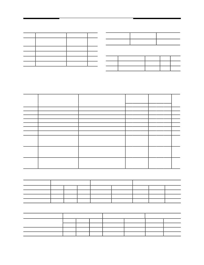
Absolute Maximum Ratings
(1)
MS7200L/01AL/02AL Rev. 1.0 January 1995
Operating Range
Capacitance
(1)
T
A
= 25°C, f = 1.0MHz
Range
Ambient
Temperature
Vcc
Commercial
0
°
C to + 70
°
C
5V
±
10%
Symbol
Parameter
Condition
Unit
V
TERM
Terminal Voltage with
Repect to GND
Temperature Under Bias
-0.5 to +7.0
V
T
BIAS
-10 to +125
°
C
T
STG
Storage Temperature
-60 to +150
°
C
P
T
Power Dissipation
1.0
W
I
OUT
DC Output Current
20
mA
Symbol
Parameter
Condition
Max.
Unit
C
IN
Input Capacitance
V
IN
= 0V
4
pF
C
Q
Output Capacitance
V
DQ
= 0V
6
pF
DC Electrical Characteristics (over the commercial operating range)
Depth Expansion/Compound Expansion Mode
NOTE:
1.
XI
is connected to
XO
of previous device. See Figure 15.
RS
= Reset Input.
FL
/
RT
= First Load/Retransmit.
EF
= Empty Flag
Output.
FF
Full Flag Output.
XI
= Expansion Input.
1.
Stresses greater than those listed under ABSOLUTE
MAXIMUM RATINGS may cause permanent damage to the
device. This is a stress rating only and functional operation
of the device at these or any other conditions above those
indicated in the operational sections of this specification is
not implied. Exposure to absolute maximum rating conditions
for extended periods may affect reliability.
Truth Tables
Single Device Configuration/Width Expansion Mode
NOTE: 1. Pointer will increment if flag is high.
Mode
Inputs
Internal Status
Outputs
RS
0
1
1
RT
X
0
1
XI
0
0
0
Read Pointer
Location Zero
Location Zero
Increment
(1)
Write Pointer
Location Zero
Unchanged
Increment
(1)
EF
0
X
X
FF
1
X
X
HF
1
X
X
Reset
Retransmit
Read/Write
Mode
Inputs
Internal Status
Outputs
RS
0
0
1
FL
0
1
X
XI
(1)
(1)
(1)
Read Pointer
Location Zero
Location Zero
X
Write Pointer
Location Zero
Unchanged
X
EF
0
0
X
FF
1
1
X
Reset-First Device
Reset all Other Devices
Read/Write
Test
MS7200L/7201AL
7202AL
(-25, -35)
Min. Typ. Max. Min.
-
-
2.0
-
-1
-10
-
-
2.4
-
-
-
-
-
MS7200L/7201AL
7202AL
(-50, -80)
Typ. Max. Units
-
-
2.0
-
-1
-10
-
-
2.4
-
-
50
-
5
Parameter
V
IL
V
IH
I
IL
I
OL
V
OL
V
OH
I
CC1
I
CC2
Parameter
Test Conditions
Input Low Voltage
Input High Voltage
Input Leakage Current
Output Leakage Current
Output Low Voltage
Output High Voltage
Operating Power Supply Current V
CC
= Max, I
I/O
= 0mA, F = F
m ax
Average Standby Current
0.8
-
1
10
0.4
-
125
15
0.8
-
1
10
0.4
-
80
8
V
V
V
CC
= Max, V
IN
= 0Vto V
CC
V
CC
= Max, R= V
IH
, V
IN
= 0V toV
CC
V
CC
= Min, I
OL
= 8mA
V
CC
= Min, I
OH
= -2mA
μ
A
μ
A
V
V
mA
mA
V
CC
= Max,
R
=
W
=
RS
=
FL
/
RT
=
V
IH
,
I
I/O
= 0mA
V
CC
= Max,
R
=
W
=
RS
=
FL
/
RT
>
V
CC
-0.2V, V
IN
> V
CC
-0.2V or V
IN
<
0.2V
V
CC
= Max,
R
=
W
=
RS
=
FL
/
RT
>
V
CC
-0.2V, V
IN
> V
CC
-0.2V or V
IN
<
0.2V
I
CCSB(S)
Power Down Power Supply
Current (Standard Power)
-
-
5
-
-
5
mA
I
CCSB(L)
Power Down Power Supply
Current (Low Power)
-
-
500
-
-
500
μ
A
相關(guān)PDF資料 |
PDF描述 |
|---|---|
| MSA1AA001 | Coils/Delay Lines |
| MSA240 | PULSE WIDTH MODULATION AMPLIFIER |
| MSA260 | PULSE WIDTH MODULATION AMPLIFIER |
| MSAER12N50A | N-CHANNEL ENHANCEMENT MODE POWER MOSFET |
| MSAFR12N50A | N-CHANNEL ENHANCEMENT MODE POWER MOSFET |
相關(guān)代理商/技術(shù)參數(shù) |
參數(shù)描述 |
|---|---|
| MS720435PC | 制造商:MOSELE 功能描述: |
| MS7204-A2 | 制造商:INTERSEMA 制造商全稱(chēng):INTERSEMA 功能描述:PRESSURE SENSOR DIE (0-4 BAR) FOR HARSH ENVIRONMENT |
| MS7207-A2 | 制造商:INTERSEMA 制造商全稱(chēng):INTERSEMA 功能描述:PRESSURE SENSOR DIE (0-7 BAR) FOR HARSH ENVIRONMENT |
| MS-721 | 制造商:DWYER INSTRUMENTS 功能描述:MS-721 + LR 0-5V WALL MT |
| MS7212 | 制造商:INTERSEMA 制造商全稱(chēng):INTERSEMA 功能描述:PRESSURE SENSOR DIE (0-12 BAR) FOR HARSH ENVIRONMENT |
發(fā)布緊急采購(gòu),3分鐘左右您將得到回復(fù)。