- 您現(xiàn)在的位置:買賣IC網(wǎng) > PDF目錄374506 > MS3470L12-32AW (ITT Corporation) Series 2 Connectors PV PDF資料下載
參數(shù)資料
| 型號(hào): | MS3470L12-32AW |
| 廠商: | ITT Corporation |
| 英文描述: | Series 2 Connectors PV |
| 中文描述: | 光伏連接器系列2 |
| 文件頁(yè)數(shù): | 2/10頁(yè) |
| 文件大小: | 500K |
| 代理商: | MS3470L12-32AW |

www.ittcannon.com
Dimensions are shown in inches (millimeters).
Dimensions subject to change.
MIL-C-26482, Series 2 Connectors PV
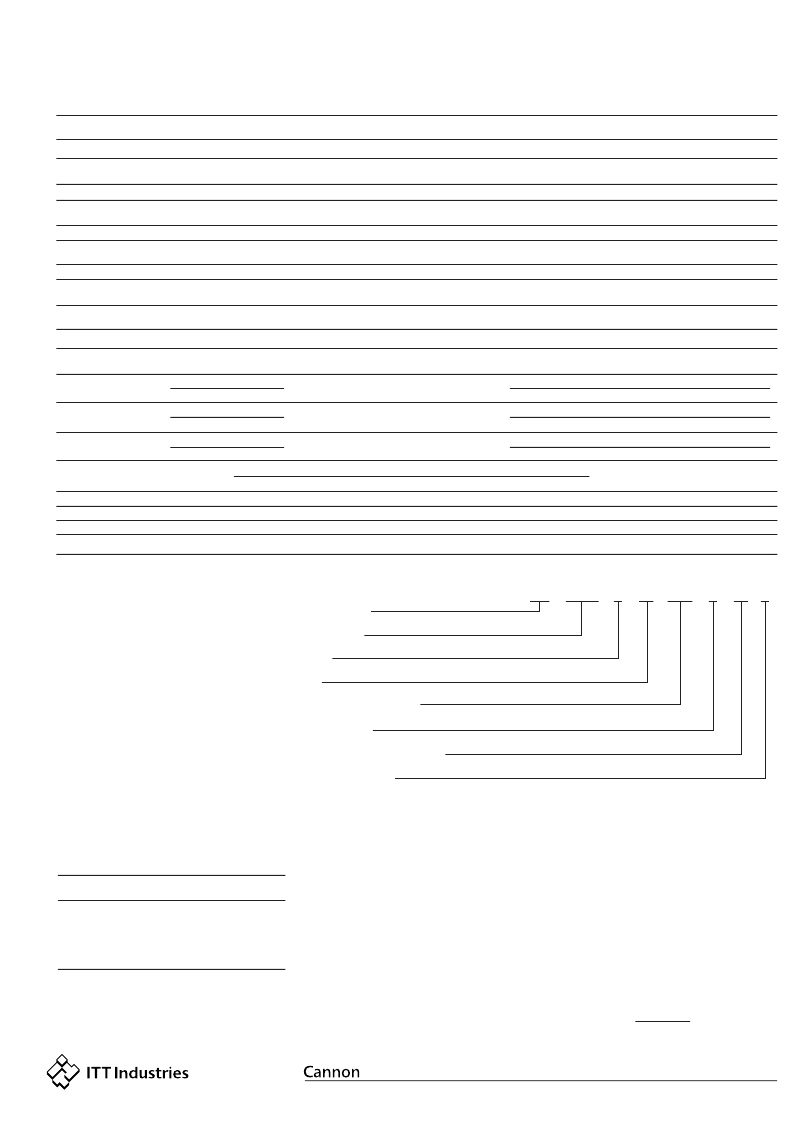
How to Order
Performance and Material Specifications
ELECTRICAL
MATERIALS AND FINISHES
Description
Shell
Aluminum alloy per QQ-A-367, QQ-A-591 or QQ-A-225
Electoless nickel per MIL-C-26074, anodized per MIL-A-8625 or olive drab
cadmium over nickel
Electoless nickel per MIL-C-26074, anodized per MIL-A-8625 or olive drab
cadmium over nickel
Electoless nickel per MIL-C-26074, anodized per MIL-A-8625 or olive drab
cadmium over nickel
Insulators
Rigid dielectric
Silicone rubber (ITT Cannon blend) or Fluorosiclicone rubber (ITT
Cannon blen)
Copper alloy
Aluminum alloy per QQ-A-591
Aluminum alloy per QQ-A-225
None
None
None
Gold page per MIL-G-45204
Elastomers (grommets, interfacial and O ring seals)
Contacts
Coupling Nut
Jam Nut (on PV74)
12
16
20
.097 (2.46)
.053 (1.53)
.040 (1.02)
.158 (4.01)
.103 (2.62)
.083 (2.11)
12
14
16
20
20
24
I
II
1500 Vac rms
2300 Vac rms
375 Vac rms
500 Vac rms
5000 megohms minimum
5000 megohms minimum
23
17
13
7.5
7.5
3.0
50
45
50
45
55
45
Contact
Size
Wire
Size
Max Current
for Test (amps)
Potential Drop
(Millivolts at 25C)
Insulation O.D. Limits, inch (mm)
min.
max.
Service Rating
Sea Level
SERIES PREFIX
PV
MS
70
3470
L
L
18
18
-32
-32
P
P
W
W
L
SHELL STYLE
CLASS
SIZE
CONTACT ARRANGEMENT
CONTACT TYPE
ALTERNATE INSERT POSITIONS
LESS COMPONENTS
CLASS
(PV Series and MS Series)
*A - Fluid resistant, 200C, non-conductive
(anodized)
L - Fluid resistant, 200C, conductive, finish
(nickely)
W - Corrosive and fluid resistant, 175C
(cadmium over nickel)
SHELL SIZE
8, 10, 12, 14, 16, 18, 20, 22 and 24
(Size 8 avialable in PV70 & 76 only)
SHELL STYLE
SERIES PREFIX
MS - Complies with MIL-C-26482 Series 2
PV - ITT Cannon Interchangeable with
MIL-C-26482, Series 2
*Consult factory for availablility.
P - Pin contact
S - Socket contact
A - Less pin contact* (MS only)
B - Less socket contacts* (MS only)
* The "A" and "B" designators are used only when other
than power contacts are ato be installed (i.e. shielded, coaxial
and thermocouple contacts).
No designation required for normal posistion.
Standard MS alternate positions available.
Use "L" if PV connectors are ordered less
contacts, sealing plugs and insertion/extraction
tool ("L" is not stamped on connectors). To
order MS connectors
less contacts
, purchase
order must state less contacts.
See page 162.
ITT Cannon
Part No.
PV70
PV71
PV72
PV74
PV75
PV76
MS3470
MS3471
MS3472
MS3474
MS3475
MS3476
- Narrow Flange Receptacle
- Cable Connecting Receptacle
- Wide Flange Receptacle
- Jam Nut Receptacle
- Straight Plug, RFI Shielded
- Straight Plug
Military No.
Description
CONTACT TYPE
ALTERNATE INSERT POSITIONS
LESS COMPONENTS
CONTACT ARRANGEMENTS
70,000 ft. Altitude
(25C)
Dielectric Withstanding Voltage (Test Volatge)
Material
Finish
相關(guān)PDF資料 |
PDF描述 |
|---|---|
| MS3470L12-32BW | Series 2 Connectors PV |
| MS3470L12-32PW | Series 2 Connectors PV |
| MS3470L12-32SW | Series 2 Connectors PV |
| MS3470L18-32AW | Series 2 Connectors PV |
| MS3470L18-32BW | Series 2 Connectors PV |
相關(guān)代理商/技術(shù)參數(shù) |
參數(shù)描述 |
|---|---|
| MS3470L12-32BW | 制造商:ITT 制造商全稱:ITT Industries 功能描述:Series 2 Connectors PV |
| MS3470L12-32PW | 制造商:ITT 制造商全稱:ITT Industries 功能描述:Series 2 Connectors PV |
| MS3470L12-32SW | 制造商:ITT 制造商全稱:ITT Industries 功能描述:Series 2 Connectors PV |
| MS3470L12-3A | 功能描述:環(huán)形MIL規(guī)格連接器 3P SZ 12 RECPT FLANGE MOUNT PIN RoHS:否 制造商:Amphenol MIL 類型:MIL-DTL-5015 系列:97 產(chǎn)品類型:Receptacles 外殼大小:28 外殼類型:Potting 觸點(diǎn)類型:Socket (Female) 位置/觸點(diǎn)數(shù)量:14 插入安排:28-2 觸點(diǎn)材料:Copper Alloy 觸點(diǎn)電鍍:Silver 安裝角:Straight 安裝風(fēng)格:Wire 端接類型:Solder 電流額定值: |
| MS3470L12-3AY | 功能描述:環(huán)形MIL規(guī)格連接器 3P SZ 12 RECPT FLANGE MOUNT PIN RoHS:否 制造商:Amphenol MIL 類型:MIL-DTL-5015 系列:97 產(chǎn)品類型:Receptacles 外殼大小:28 外殼類型:Potting 觸點(diǎn)類型:Socket (Female) 位置/觸點(diǎn)數(shù)量:14 插入安排:28-2 觸點(diǎn)材料:Copper Alloy 觸點(diǎn)電鍍:Silver 安裝角:Straight 安裝風(fēng)格:Wire 端接類型:Solder 電流額定值: |
發(fā)布緊急采購(gòu),3分鐘左右您將得到回復(fù)。