- 您現(xiàn)在的位置:買賣IC網(wǎng) > PDF目錄299509 > MQFL-28E-12S-Y-C (SYNQOR INC) 1-OUTPUT 120 W DC-DC REG PWR SUPPLY MODULE PDF資料下載
參數(shù)資料
| 型號: | MQFL-28E-12S-Y-C |
| 廠商: | SYNQOR INC |
| 元件分類: | 電源模塊 |
| 英文描述: | 1-OUTPUT 120 W DC-DC REG PWR SUPPLY MODULE |
| 封裝: | MODULE-12 |
| 文件頁數(shù): | 17/17頁 |
| 文件大?。?/td> | 1050K |
| 代理商: | MQFL-28E-12S-Y-C |
Product # MQFL-28E-12S
Phone 1-888-567-9596
www.synqor.com
Doc.# 005-0005104 Rev. A
07/28/09
Page 9
Output:
Current:
12V
10A
MQFL-28E-12S
Technical Specification
BASIC OPERATION AND FEATURES
The MQFL DC/DC converter uses a two-stage power conversion
topology. The first, or regulation, stage is a buck-converter that
keeps the output voltage constant over variations in line, load,
and temperature. The second, or isolation, stage uses transform-
ers to provide the functions of input/output isolation and voltage
transformation to achieve the output voltage required.
Both the regulation and the isolation stages switch at a fixed
frequency for predictable EMI performance. The isolation stage
switches at one half the frequency of the regulation stage, but due
to the push-pull nature of this stage it creates a ripple at double its
switching frequency. As a result, both the input and the output of
the converter have a fundamental ripple frequency of about 550
kHz in the free-running mode.
Rectification of the isolation stage’s output is accomplished with
synchronous rectifiers. These devices, which are MOSFETs with a
very low resistance, dissipate far less energy than would Schottky
diodes. This is the primary reason why the MQFL converters have
such high efficiency, particularly at low output voltages.
Besides improving efficiency, the synchronous rectifiers permit
operation down to zero load current. There is no longer a need
for a minimum load, as is typical for converters that use diodes for
rectification. The synchronous rectifiers actually permit a nega-
tive load current to flow back into the converter’s output terminals
if the load is a source of short or long term energy. The MQFL
converters employ a “back-drive current limit” to keep this nega-
tive output terminal current small.
There is a control circuit on both the input and output sides of the
MQFL converter that determines the conduction state of the power
switches. These circuits communicate with each other across the
isolation barrier through a magnetically coupled device. No
opto-isolators are used.
A separate bias supply provides power to both the input and out-
put control circuits. Among other things, this bias supply permits
the converter to operate indefinitely into a short circuit and to
avoid a hiccup mode, even under a tough start-up condition.
An input under-voltage lockout feature with hysteresis is provided,
as well as an input over-voltage shutdown. There is also an
output current limit that is nearly constant as the load impedance
decreases to a short circuit (i.e., there is not fold-back or fold-
forward characteristic to the output current under this condition).
When a load fault is removed, the output voltage rises exponen-
tially to its nominal value without an overshoot.
The MQFL converter’s control circuit does not implement an output
over-voltage limit or an over-temperature shutdown.
The following sections describe the use and operation of addi-
tional control features provided by the MQFL converter.
CONTROL FEATURES
ENABLE: The MQFL converter has two enable pins. Both must
have a logic high level for the converter to be enabled. A logic
low on either pin will inhibit the converter.
The ENA1 pin (pin 4) is referenced with respect to the converter’s
input return (pin 2). The ENA2 pin (pin 12) is referenced with
respect to the converter’s output return (pin 8). This permits the
converter to be inhibited from either the input or the output side.
Regardless of which pin is used to inhibit the converter, the regu-
lation and the isolation stages are turned off. However, when
the converter is inhibited through the ENA1 pin, the bias supply
is also turned off, whereas this supply remains on when the con-
verter is inhibited through the ENA2 pin. A higher input standby
current therefore results in the latter case.
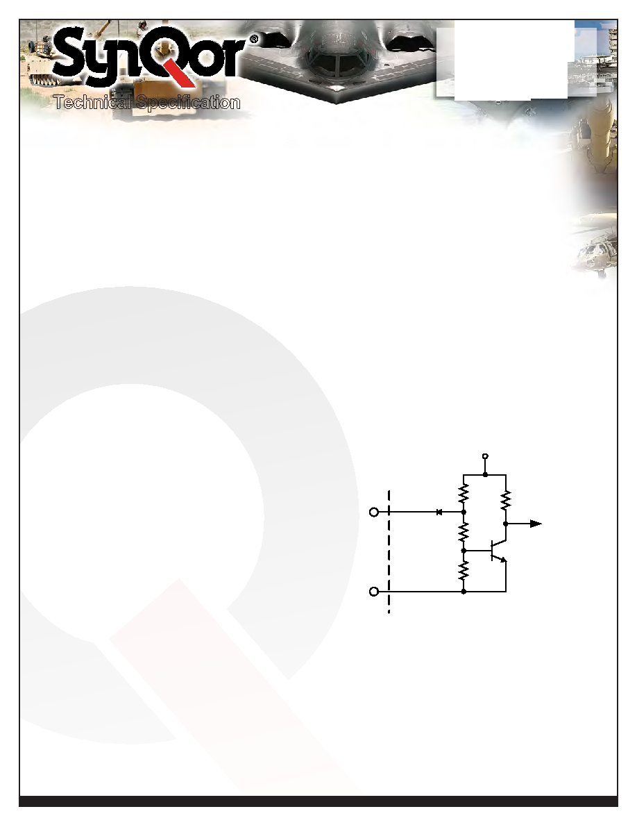
Both enable pins are internally pulled high so that an open con-
nection on both pins will enable the converter. Figure A shows
the equivalent circuit looking into either enable pins. It is TTL
compatible.
SHUT DOWN: The MQFL converter will shut down in response
to only four conditions: ENA1 input low, ENA2 input low, VIN
input below under-voltage lockout threshold, or VIN input above
over-voltage shutdown threshold. Following a shutdown event,
there is a startup inhibit delay which will prevent the converter
from restarting for approximately 300ms. After the 300ms delay
elapses, if the enable inputs are high and the input voltage is
within the operating range, the converter will restart. If the VIN
input is brought down to nearly 0V and back into the operating
range, there is no startup inhibit, and the output voltage will rise
according to the “Turn-On Delay, Rising Vin” specification.
N3904
N4148
250K
125K
82K
5.6V
TO ENABLE
CIRCUITRY
PIN 4
(or PIN 12)
PIN 2
(or PIN 8)
IN RTN
ENABLE
Figure A:
Equivalent circuit looking into either the ENA1 or ENA2
pins with respect to its corresponding return pin.
相關(guān)PDF資料 |
PDF描述 |
|---|---|
| MQHL-28-05D-W-ES | 2-OUTPUT 50 W DC-DC REG PWR SUPPLY MODULE |
| MQHL-28-2R5S-X-ES | 1-OUTPUT 50 W DC-DC REG PWR SUPPLY MODULE |
| MQHL-28E-15D-Z-C | 2-OUTPUT 50 W DC-DC REG PWR SUPPLY MODULE |
| MR27V25603L-XXXTME | 16M X 16 MASK PROM, 120 ns, PDSO50 |
| MR4027P | UNIDIRECTIONAL, SILICON, TVS DIODE |
相關(guān)代理商/技術(shù)參數(shù) |
參數(shù)描述 |
|---|---|
| MQFL-28E-12S-Y-ES | 制造商:SYNQOR 制造商全稱:SYNQOR 功能描述:HIGH RELIABILITY DC-DC CONVERTER |
| MQFL-28E-15S | 制造商:SYNQOR 制造商全稱:SYNQOR 功能描述:HIGH RELIABILITY DC-DC CONVERTER |
| MQFL-28E-15S-Y-ES | 制造商:SYNQOR 制造商全稱:SYNQOR 功能描述:HIGH RELIABILITY DC-DC CONVERTER |
| MQFL-28E-1R5S | 制造商:SYNQOR 制造商全稱:SYNQOR 功能描述:HIGH RELIABILITY DC-DC CONVERTER |
| MQFL-28E-1R5S-Y-ES | 制造商:SYNQOR 制造商全稱:SYNQOR 功能描述:HIGH RELIABILITY DC-DC CONVERTER |
發(fā)布緊急采購,3分鐘左右您將得到回復(fù)。