- 您現(xiàn)在的位置:買賣IC網(wǎng) > PDF目錄25623 > MQ80C52XXX-36SHXXX (ATMEL CORP) 8-BIT, MROM, 36 MHz, MICROCONTROLLER, CQFP44 PDF資料下載
參數(shù)資料
| 型號: | MQ80C52XXX-36SHXXX |
| 廠商: | ATMEL CORP |
| 元件分類: | 微控制器/微處理器 |
| 英文描述: | 8-BIT, MROM, 36 MHz, MICROCONTROLLER, CQFP44 |
| 封裝: | CERAMIC, QFP-44 |
| 文件頁數(shù): | 63/132頁 |
| 文件大小: | 10886K |
| 代理商: | MQ80C52XXX-36SHXXX |
第1頁第2頁第3頁第4頁第5頁第6頁第7頁第8頁第9頁第10頁第11頁第12頁第13頁第14頁第15頁第16頁第17頁第18頁第19頁第20頁第21頁第22頁第23頁第24頁第25頁第26頁第27頁第28頁第29頁第30頁第31頁第32頁第33頁第34頁第35頁第36頁第37頁第38頁第39頁第40頁第41頁第42頁第43頁第44頁第45頁第46頁第47頁第48頁第49頁第50頁第51頁第52頁第53頁第54頁第55頁第56頁第57頁第58頁第59頁第60頁第61頁第62頁當(dāng)前第63頁第64頁第65頁第66頁第67頁第68頁第69頁第70頁第71頁第72頁第73頁第74頁第75頁第76頁第77頁第78頁第79頁第80頁第81頁第82頁第83頁第84頁第85頁第86頁第87頁第88頁第89頁第90頁第91頁第92頁第93頁第94頁第95頁第96頁第97頁第98頁第99頁第100頁第101頁第102頁第103頁第104頁第105頁第106頁第107頁第108頁第109頁第110頁第111頁第112頁第113頁第114頁第115頁第116頁第117頁第118頁第119頁第120頁第121頁第122頁第123頁第124頁第125頁第126頁第127頁第128頁第129頁第130頁第131頁第132頁
268
8151H–AVR–02/11
ATmega128A
Note:
Incorrect setting of the switches in Figure 24-13 will make signal contention and may damage the
part. There are several input choices to the S&H circuitry on the negative input of the output com-
parator in Figure 24-13. Make sure only one path is selected from either one ADC pin, Bandgap
reference source, or Ground.
If the ADC is not to be used during scan, the recommended input values from Table 24-5 should
be used. The user is recommended not to use the Differential Gain stages during scan. Switch-
Cap based gain stages require fast operation and accurate timing which is difficult to obtain
when used in a scan chain. Details concerning operations of the differential gain stage is there-
fore not provided.
The AVR ADC is based on the analog circuitry shown in Figure 24-13 with a successive approx-
imation algorithm implemented in the digital logic. When used in Boundary-scan, the problem is
usually to ensure that an applied analog voltage is measured within some limits. This can easily
be done without running a successive approximation algorithm: apply the lower limit on the digi-
tal DAC[9:0] lines, make sure the output from the comparator is low, then apply the upper limit
on the digital DAC[9:0] lines, and verify the output from the comparator to be high.
The ADC need not be used for pure connectivity testing, since all analog inputs are shared with
a digital port pin as well.
When using the ADC, remember the following
The Port Pin for the ADC channel in use must be configured to be an input with pull-up
disabled to avoid signal contention.
In normal mode, a dummy conversion (consisting of 10 comparisons) is performed when
enabling the ADC. The user is advised to wait at least 200ns after enabling the ADC before
controlling/observing any ADC signal, or perform a dummy conversion before using the first
result.
The DAC values must be stable at the midpoint value 0x200 when having the HOLD signal
low (Sample mode).
As an example, consider the task of verifying a 1.5V ±5% input signal at ADC channel 3 when
the power supply is 5.0V and AREF is externally connected to V
CC.
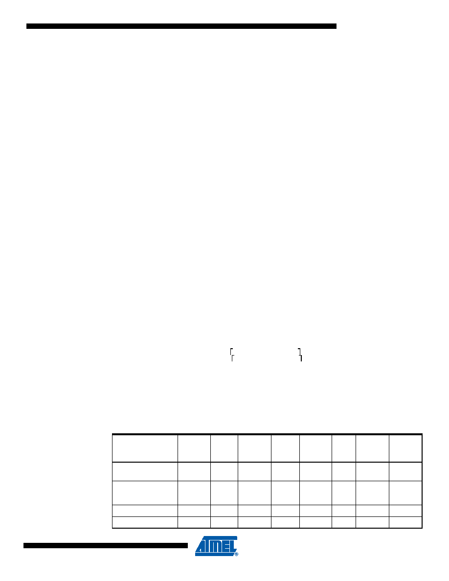
The recommended values from Table 24-5 are used unless other values are given in the algo-
rithm in Table 24-6. Only the DAC and Port Pin values of the Scan Chain are shown. The
column “Actions” describes what JTAG instruction to be used before filling the Boundary-scan
Register with the succeeding columns. The verification should be done on the data scanned out
when scanning in the data on the same row in the table.
Table 24-6.
Algorithm for Using the ADC
Step
Actions
ADCEN
DAC
MUXEN
HOLD
PRECH
PA3.
Data
PA3.
Control
PA3.
Pullup_
Enable
1
SAMPLE_P
RELOAD
1
0x200
0x08
1
0
2
EXTEST
1
0x200
0x08
0
1
0
3
1
0x200
0x08
1
0
4
1
0x123
0x08
1
0
5
1
0x123
0x08
1
0
The lower limit is:
1024 1.5
V 0,95 5V
291
0x123
==
The upper limit is:
1024 1.5
V 1.05 5V
323
0x143
==
相關(guān)PDF資料 |
PDF描述 |
|---|---|
| MC80C32E-16SHXXX:D | 8-BIT, 16 MHz, MICROCONTROLLER, CDIP40 |
| MR80C52XXX-36SCD | 8-BIT, MROM, 36 MHz, MICROCONTROLLER, CQCC44 |
| MD80C32-16SHXXX | 8-BIT, 16 MHz, MICROCONTROLLER, CDIP40 |
| MR80C32E-20/883:RD | 8-BIT, 20 MHz, MICROCONTROLLER, CQCC44 |
| MR80C52XXX-30SCR | 8-BIT, MROM, 30 MHz, MICROCONTROLLER, CQCC44 |
相關(guān)代理商/技術(shù)參數(shù) |
參數(shù)描述 |
|---|---|
| MQ82370-20 | 制造商:Rochester Electronics LLC 功能描述:- Bulk |
| MQ8238020 | 制造商:Intel 功能描述:CONTROLLER: OTHER |
| MQ82380-20 | 制造商:Rochester Electronics LLC 功能描述:- Bulk |
| MQ82380-20/R | 制造商:Rochester Electronics LLC 功能描述: |
| MQ82592 | 制造商:Rochester Electronics LLC 功能描述:- Bulk |
發(fā)布緊急采購,3分鐘左右您將得到回復(fù)。