- 您現(xiàn)在的位置:買賣IC網(wǎng) > PDF目錄359188 > MPC5534 (飛思卡爾半導(dǎo)體(中國)有限公司) Microcontroller PDF資料下載
參數(shù)資料
| 型號: | MPC5534 |
| 廠商: | 飛思卡爾半導(dǎo)體(中國)有限公司 |
| 英文描述: | Microcontroller |
| 中文描述: | 微控制器 |
| 文件頁數(shù): | 5/50頁 |
| 文件大?。?/td> | 1148K |
| 代理商: | MPC5534 |
第1頁第2頁第3頁第4頁當(dāng)前第5頁第6頁第7頁第8頁第9頁第10頁第11頁第12頁第13頁第14頁第15頁第16頁第17頁第18頁第19頁第20頁第21頁第22頁第23頁第24頁第25頁第26頁第27頁第28頁第29頁第30頁第31頁第32頁第33頁第34頁第35頁第36頁第37頁第38頁第39頁第40頁第41頁第42頁第43頁第44頁第45頁第46頁第47頁第48頁第49頁第50頁

Electrical Characteristics
MPC5534 Microcontroller Data Sheet, Rev. 0
Preliminary—Subject to Change Without Notice
Freescale Semiconductor
5
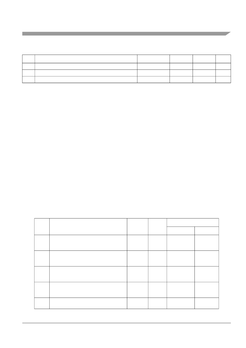
3.2
Thermal Characteristics
27
Storage Temperature Range
Maximum Solder Temperature
13
Moisture Sensitivity Level
14
T
STG
T
SDR
MSL
– 55.0
150.0
o
C
28
—
260.0
o
C
29
—
3
1
Functional operating conditions are given in the DC electrical specifications. Absolute maximum ratings are stress ratings only,
and functional operation at the maxima is not guaranteed. Stress beyond the listed maxima may affect device reliability or
cause permanent damage to the device.
2
Absolute maximum voltages are currently maximum burn-in voltages. Absolute maximum specifications for device stress have
not yet been determined.
3
1.5V +/– 10% for proper operation. This parameter is specified at a maximum junction temperature of 150C.
4
All functional non-supply I/O pins are clamped to VSS and VDDE or VDDEH.
5
AC signal over and undershoot of the input voltages of up to +/– 2.0 volts is permitted for a cumulative duration of 60 hours
over the complete lifetime of the device (injection current does not need to be limited for this duration).
6
Internal structures will hold the voltage above –1.0 volt if the injection current limit of 2 mA is met.
7
Internal structures will not clamp to a safe voltage. External protection must be used to ensure that voltage on the pin stays
above –0.3 volts.
8
Internal structures hold the input voltage below this maximum voltage on all pads powered by VDDEH supplies, if the maximum
injection current specification is met (2 mA for all pins) and VDDEH is within Operating Voltage specifications.
9
Internal structures hold the input voltage below this maximum voltage on all pads powered by VDDE supplies, if the maximum
injection current specification is met (2 mA for all pins) and VDDE is within Operating Voltage specifications.
10
Total injection current for all pins (including both digital and analog) must not exceed 25mA.
11
Total injection current for all analog input pins must not exceed 15mA.
12
Lifetime operation at these specification limits is not guaranteed.
13
Solder profile per CDF-AEC-Q100.
14
Moisture sensitivity per JEDEC test method A112.
Table 3. Thermal Characteristics
Num
Characteristic
Symbol
Unit
Value
208 MAPBGA
324 PBGA
1
Junction to Ambient
1, 2
Natural Convection
(Single layer board)
Junction to Ambient
1, 3
Natural Convection
(Four layer board 2s2p)
R
θ
JA
°C/W
42
34
2
R
θ
JA
°C/W
26
23
3
Junction to Ambient
(@200 ft./min.,
Single layer board)
R
θ
JMA
°C/W
34
28
4
Junction to Ambient
(@200 ft./min.,
Four layer board 2s2p)
Junction to Board
4
(Four layer board 2s2p)
R
θ
JMA
°C/W
22
20
5
R
θ
JB
°C/W
15
15
Table 2. Absolute Maximum Ratings
1
(continued)
Num
Characteristic
Symbol
Min
Max
2
Unit
相關(guān)PDF資料 |
PDF描述 |
|---|---|
| MPC7447A | PowerPC microprocessor |
| MPC7447ANXPNS | PowerPC microprocessor |
| MPC7455 | RISC Microprocessor Hardware Specifications |
| MPC7457 | RISC Microprocessor Hardware Specifications |
| MPC7457EC | RISC Microprocessor Hardware Specifications |
相關(guān)代理商/技術(shù)參數(shù) |
參數(shù)描述 |
|---|---|
| MPC5534AVF40 | 制造商:FREESCALE 制造商全稱:Freescale Semiconductor, Inc 功能描述:Microcontroller |
| MPC5534AVF40R2 | 制造商:FREESCALE 制造商全稱:Freescale Semiconductor, Inc 功能描述:Microcontroller |
| MPC5534AVF66 | 制造商:FREESCALE 制造商全稱:Freescale Semiconductor, Inc 功能描述:Microcontroller |
| MPC5534AVF66R2 | 制造商:FREESCALE 制造商全稱:Freescale Semiconductor, Inc 功能描述:Microcontroller |
| MPC5534AVF80 | 制造商:FREESCALE 制造商全稱:Freescale Semiconductor, Inc 功能描述:Microcontroller |
發(fā)布緊急采購,3分鐘左右您將得到回復(fù)。