- 您現(xiàn)在的位置:買賣IC網(wǎng) > PDF目錄359729 > MMA6263QR2 (MOTOROLA INC) 【1.5g Dual Axis Micromachined Accelerometer PDF資料下載
參數(shù)資料
| 型號: | MMA6263QR2 |
| 廠商: | MOTOROLA INC |
| 元件分類: | 模擬信號調(diào)理 |
| 英文描述: | 【1.5g Dual Axis Micromachined Accelerometer |
| 中文描述: | SPECIALTY ANALOG CIRCUIT, QCC16 |
| 封裝: | 6 X 6 MM, 1.98 MM HEIGHT, QFN-16 |
| 文件頁數(shù): | 3/8頁 |
| 文件大?。?/td> | 124K |
| 代理商: | MMA6263QR2 |
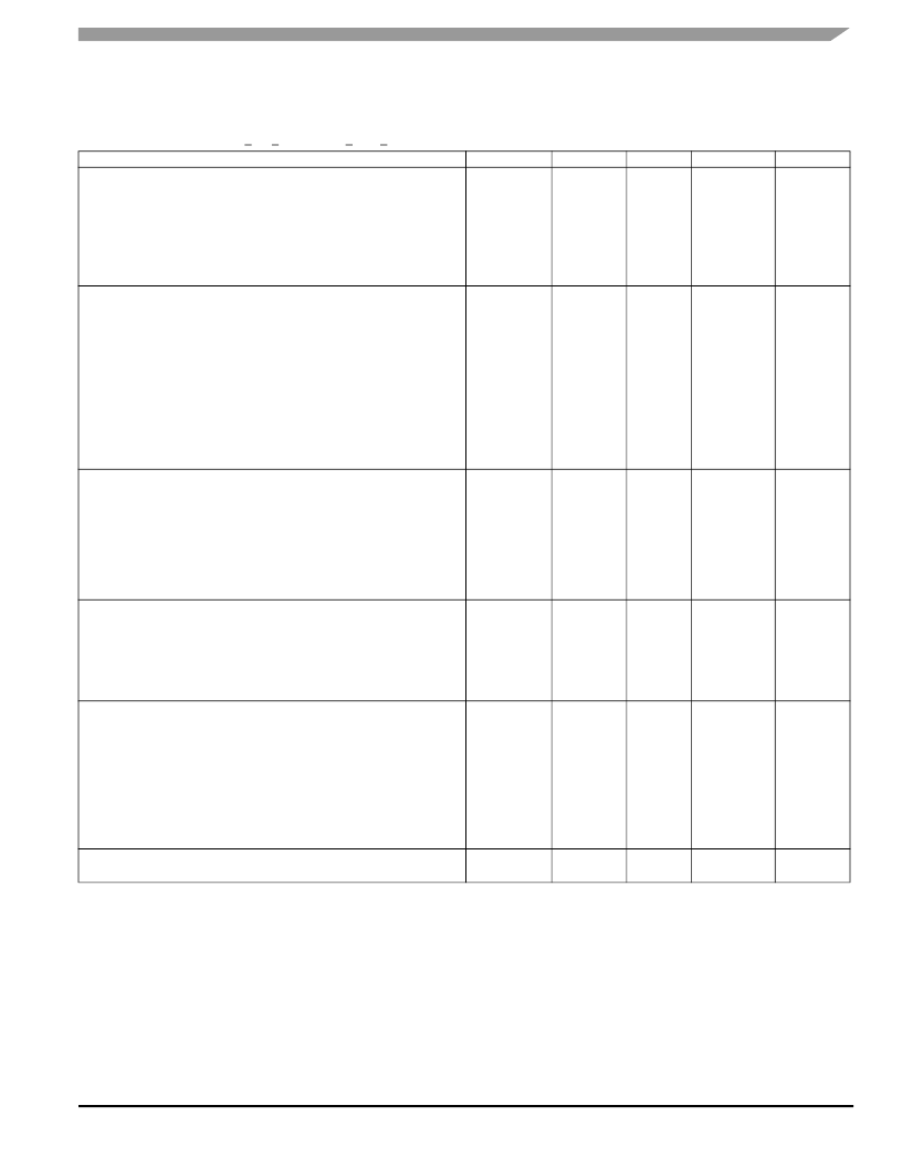
Sensor Device Data
Freescale Semiconductor
3
MMA6200 SERIES
Operating Characteristics
Unless otherwise noted: -20°C < T
A
< 85°C, 3.0 V < V
DD
< 3.6 V, Acceleration = 0g, Loaded output
1
Characteristic
Operating Range
2
Supply Voltage
3
Supply Current
MMA6260Q, MMA6261Q
MMA6262Q, MMA6263Q
Operating Temperature Range
Acceleration Range
Output Signal
Zero g (T
A
= 25°C, V
DD
= 3.3 V)
4
Zero g
Sensitivity (T
A
= 25°C, V
DD
= 3.3 V)
Sensitivity
Bandwidth Response
MMA6260Q
MMA6261Q
MMA6262Q
MMA6263Q
Nonlinearity
Noise
MMA6260Q RMS (0.1 Hz – 1 kHz)
MMA6261Q RMS (0.1 Hz – 1 kHz)
MMA6262Q RMS (0.1 Hz – 1 kHz)
MMA6263Q RMS (0.1 Hz – 1 kHz)
Power Spectral Density RMS (0.1 Hz – 1 kHz)
MMA6260Q, MMA6261Q
MMA6262Q, MMA6263Q
Self-Test
Output Response
Input Low
Input High
Pull-Down Resistance
5
Response Time
6
Output Stage Performance
Full-Scale Output Range (I
OUT
= 200 μA)
Capacitive Load Drive
7
Output Impedance
Power-Up Response Time
MMA6260Q
MMA6261Q
MMA6262Q
MMA6263Q
Mechanical Characteristics
Transverse Sensitivity
8
Notes:
1. For a loaded output, the measurements are observed after an RC filter consisting of a 1.0 k
resistor and a 0.1 μF capacitor to ground.
2. These limits define the range of operation for which the part will meet specification.
3. Within the supply range of 2.7 and 3.6 V, the device operates as a fully calibrated linear accelerometer. Beyond these supply limits the device
may operate as a linear device but is not guaranteed to be in calibration.
4. The device can measure both + and - acceleration. With no input acceleration the output is at midsupply. For positive acceleration the output
will increase above V
DD
/2. For negative acceleration, the output will decrease below V
DD
/2.
5. The digital input pin has an internal pull-down resistance to prevent inadvertent self-test initiation due to external board level leakages.
6. Time for the output to reach 90% of its final value after a self-test is initiate.
7. Preserves phase margin (60°) to guarantee output amplifier stability.
8. A measure of the device’s ability to reject an acceleration applied 90° from the true axis of sensitivity.
Symbol
Min
Typ
Max
Unit
V
DD
2.7
3.3
3.6
V
I
DD
I
DD
T
A
g
FS
—
—
-20
—
1.2
2.2
—
1.5
1.5
3.0
+85
—
mA
mA
°C
g
V
OFF
V
OFF
, T
A
S
S, T
A
1.485
—
740
—
1.65
2.0
800
0.015
1.815
—
860
—
V
mg/°C
mV/g
%/°C
f
_3dB
f
_3dB
f
_3dB
f
_3dB
NL
OUT
—
—
—
—
-1.0
50
300
150
900
—
—
—
—
—
+1.0
Hz
Hz
Hz
Hz
% FSO
n
RMS
n
RMS
n
RMS
n
RMS
—
—
—
—
1.8
3.5
1.3
2.5
—
—
—
—
mVrms
n
PSD
n
PSD
—
—
300
200
—
—
ug/
√
Hz
V
ST
V
IL
V
IH
R
PO
t
ST
0.9 V
DD
—
0.7 V
DD
43
—
—
—
—
57
2.0
V
DD
0.3 V
DD
V
DD
71
—
V
V
V
k
ms
V
FSO
C
L
Z
O
V
SS
+0.25
—
—
—
—
50
V
DD
-0.25
100
300
V
pF
t
RESPONSE
t
RESPONSE
t
t
RESPONSE
—
—
—
—
14
2.0
4.0
0.7
—
—
—
—
ms
ms
ms
ms
V
ZX
,
YX
,
ZY
-5.0
—
+5.0
% FSO
相關(guān)PDF資料 |
PDF描述 |
|---|---|
| MC9328MX21DVH | i.MX family of microprocessors |
| MC9328MX21DVK | i.MX family of microprocessors |
| MC9328MX21DVM | i.MX family of microprocessors |
| MC9328MX21VG | i.MX family of microprocessors |
| MC9328MX21VH | i.MX family of microprocessors |
相關(guān)代理商/技術(shù)參數(shù) |
參數(shù)描述 |
|---|---|
| MMA6263QT | 制造商:Freescale Semiconductor 功能描述: |
| MMA6270Q | 功能描述:加速計 - 板上安裝 2.2-3.6 VOLT RoHS:否 制造商:Murata 傳感軸:Double 加速:12 g 靈敏度: 封裝 / 箱體: 輸出類型:Analog 數(shù)字輸出 - 位數(shù):11 bit 電源電壓-最大:5.25 V 電源電壓-最小:4.75 V 電源電流:4 mA 最大工作溫度:+ 125 C 最小工作溫度:- 40 C |
| MMA6270QR2 | 功能描述:加速計 - 板上安裝 1.5 XY QFN 16 LEADS RoHS:否 制造商:Murata 傳感軸:Double 加速:12 g 靈敏度: 封裝 / 箱體: 輸出類型:Analog 數(shù)字輸出 - 位數(shù):11 bit 電源電壓-最大:5.25 V 電源電壓-最小:4.75 V 電源電流:4 mA 最大工作溫度:+ 125 C 最小工作溫度:- 40 C |
| MMA6270QT | 功能描述:加速計 - 板上安裝 1.5G XY QFN 16 LD RoHS:否 制造商:Murata 傳感軸:Double 加速:12 g 靈敏度: 封裝 / 箱體: 輸出類型:Analog 數(shù)字輸出 - 位數(shù):11 bit 電源電壓-最大:5.25 V 電源電壓-最小:4.75 V 電源電流:4 mA 最大工作溫度:+ 125 C 最小工作溫度:- 40 C |
| MMA6270QT | 制造商:Freescale Semiconductor 功能描述:IC ACCELERATION SENSOR XY 1.5G |
發(fā)布緊急采購,3分鐘左右您將得到回復(fù)。