- 您現(xiàn)在的位置:買賣IC網(wǎng) > PDF目錄374451 > MKT050102F101T (Sharma Electro Components Inc.) FILM CAPACITORS PDF資料下載
參數(shù)資料
| 型號: | MKT050102F101T |
| 廠商: | Sharma Electro Components Inc. |
| 英文描述: | FILM CAPACITORS |
| 中文描述: | 薄膜電容器 |
| 文件頁數(shù): | 5/29頁 |
| 文件大小: | 1151K |
| 代理商: | MKT050102F101T |
第1頁第2頁第3頁第4頁當前第5頁第6頁第7頁第8頁第9頁第10頁第11頁第12頁第13頁第14頁第15頁第16頁第17頁第18頁第19頁第20頁第21頁第22頁第23頁第24頁第25頁第26頁第27頁第28頁第29頁
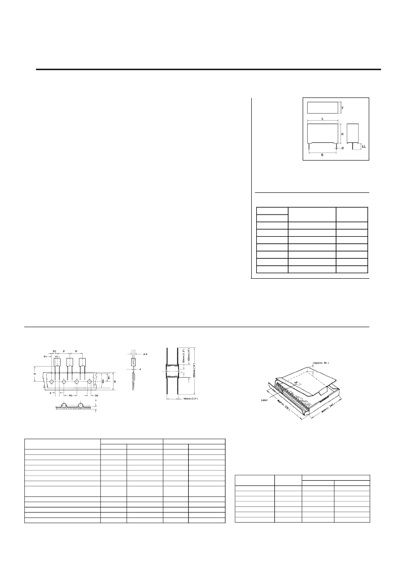
BOX SIZE
T x H x L
2.5 x 6.5 x 7.2
3.0 x 6.5 x 7.2
3.5 x 7.5 x 7.2
4.5 x 9.5 x 7.2
5.0 x 10.0 x 7.2
6.0 x 11.0 x 7.2
7.2 x 13.0 x 7.2
BULK
CARTON
3000
3000
2000
1500
1000
2000
1500
TAPED
REEL PACK
2500
2100
1800
1400
1200
1000
800
AMMO
PACK
3500
2900
2500
1900
NA
NA
NA
Taping Dimensions for MKT 050 Series (5mm Pitch)
DESCRIPTION
DIMENSION
TOLERANCES
m m
Inches
m m
±0.05
±1
±0.2
±0.7
±1.3
+0.6/ -1.1 +0.024/ -0.043
±2
±0.5
Inches
±0.002
±0.039
±0.008
±0.028
±0.051
d Lead ire ia.
P Taping itch
P0 Sprocket ole itch
P1 Centering f ead ire
P2 Centering f he ody
p Lead pacing
dS Component alignment
H Height from Sproket
Center to component body
W
Tape width
W0 Width f dhesive ape
W1 Sprocket ole lignment
D0 Position ole iameter
t Tape hickness
0.5 to 0.6 0.020 to 0.024
12.7
12.7
3.85
6.35
5
0
16.0, 16.5
0.630, 0.650
or 18.5
18
6 min.
9
4
0.7
0.500
0.500
0.152
0.250
0.197
0.000
±0.079
±0.020
or 0.728
0.709
0.236 min.
0.354
0.157
0.028
+1.0/ -0.5 +0.039/ -0.020
±0.5
±0.2
±0.2
±0.020
±0.008
±0.008
Packaging Specifications
Bulk, Tape/Reel & Ammo Pack
INTRODUCTION
The MKT 050 Series Metallized Polyester Film Capacitors are miniature capacitors with 5 mm
lead spacing. This series covers a wide range of values and voltages and exhibit excellent
high frequency characteristics. In addition to specific applications such as Blocking, By-
passing and Coupling, this series is widely used in all General Purpose applications.
FEATURES
Wide value and Voltage range
Ultra miniature size
Flame retardant case and potting
Consistent dimensions and surface finish due to molded case construction
Available in tape & reel form for automatic insertion
Self healing capability
GENERAL SPECIFICATIONS:
Dissipation factor:
For capacitance
≤
0.1 μF = 0.010 max at 1 KHz, 0.015 max at 10 KHz,
0.030 max at 100 KHz. For capacitance > 0.1 μF = 0.0010 max at 1 KHz, 0.0015 max at
10 KHz.
Insulation resistance:
For nominal voltage < 100 V DC;
≥
10,000 M Ohms
for C
≤
0.10 μF,
≥
1,000 seconds for C> 0.10 μF. For nominal voltage
≤
100 V DC;
≥
30,000
M Ohms for C
≤
0.10 μF,
≥
1,000 seconds for C> 0.10 μF at a temperature of 25 ± 5°C.
Capacitance tolerance:
±5%(J), ±10%(K) and ±20%(M)
Voltage Test:
1.6 times the rated
voltage applied between terminals for 2 seconds at a temperature of 25 ± 5 °C
Temperature range:
-55 to 100 °C with derating above 85 °C
Climatic category:
F M D
DIMENSIONS
AND
TOLERANCES:
"d"
=
0.5 to 0.6mm
(0.020 to 0.024")
for dimension
“T”
≤
3.5mm
(0.138”)
"d"
=
0.6 mm (0.024")
for dimension “T” >3.5mm (0.138”)
"LL''
=
4.0 +1.5mm(0.16 +0.06")for Bulk Supply
MKT 050
F
F
o
o
r
r
m
m
e
e
r
r
l
l
y
y
M
M
K
K
T
T
1
1
.
.
8
8
5
5
s
s
e
e
r
r
i
i
e
e
s
s
SERIES
RATED
VOLTAGE
50
63
100
100
100
250
400
Capacitance
RangeμF
0.001-1.0
0.001-1.0
>0.0068
0.0033-0.0068
>0.0033
0.001-1.0
0.001-1.0
dv/dt
value
4
8
10
15
30
20
40
PULSE RISE TIME (dv/dt) Volts per μsec.
LIFE TEST DETAILS:
Capacitors shall withstand 125% DC rated voltage or 100% AC rated voltage applied at 85 °C for 1000 hours. After the test:
1.
Capacitance change shall remain within ±5%.
2.
Dissipation Factor shall be within 1.5 times the original limits.
3.
Insulation Resistance shall be above 50% of the initial limits.
4.
There shall be no remarkable change in the appearance and the marking shall remain legible.
Sharma Film Capacitors
相關PDF資料 |
PDF描述 |
|---|---|
| MKT050102F251 | FILM CAPACITORS |
| MKT050102F251A | FILM CAPACITORS |
| MKT050102F251T | FILM CAPACITORS |
| MKT050102F500 | FILM CAPACITORS |
| MKT050102F500A | FILM CAPACITORS |
相關代理商/技術(shù)參數(shù) |
參數(shù)描述 |
|---|---|
| MKT050102F251 | 制造商:SHARMA 制造商全稱:Sharma Electro Components,Inc 功能描述:FILM CAPACITORS |
| MKT050102F251A | 制造商:SHARMA 制造商全稱:Sharma Electro Components,Inc 功能描述:FILM CAPACITORS |
| MKT050102F251T | 制造商:SHARMA 制造商全稱:Sharma Electro Components,Inc 功能描述:FILM CAPACITORS |
| MKT050102F500 | 制造商:SHARMA 制造商全稱:Sharma Electro Components,Inc 功能描述:FILM CAPACITORS |
| MKT050102F500A | 制造商:SHARMA 制造商全稱:Sharma Electro Components,Inc 功能描述:FILM CAPACITORS |
發(fā)布緊急采購,3分鐘左右您將得到回復。