- 您現(xiàn)在的位置:買(mǎi)賣(mài)IC網(wǎng) > PDF目錄383606 > MIC2580 (Micrel Semiconductor,Inc.) Hot-Swap PCI Power Controller(熱交換PCI功率控制器) PDF資料下載
參數(shù)資料
| 型號(hào): | MIC2580 |
| 廠(chǎng)商: | Micrel Semiconductor,Inc. |
| 元件分類(lèi): | 基準(zhǔn)電壓源/電流源 |
| 英文描述: | Hot-Swap PCI Power Controller(熱交換PCI功率控制器) |
| 中文描述: | 熱插拔PCI電源控制器(熱交換的PCI功率控制器) |
| 文件頁(yè)數(shù): | 19/24頁(yè) |
| 文件大?。?/td> | 288K |
| 代理商: | MIC2580 |
第1頁(yè)第2頁(yè)第3頁(yè)第4頁(yè)第5頁(yè)第6頁(yè)第7頁(yè)第8頁(yè)第9頁(yè)第10頁(yè)第11頁(yè)第12頁(yè)第13頁(yè)第14頁(yè)第15頁(yè)第16頁(yè)第17頁(yè)第18頁(yè)當(dāng)前第19頁(yè)第20頁(yè)第21頁(yè)第22頁(yè)第23頁(yè)第24頁(yè)
July 2000
19
MIC2580
MIC2580
Application Information
Whenever voltage is applied to a highly capacitive load, high
inrush currents may result in voltage droop that may bring the
supply voltage out of regulation for the duration of the
transient. The MIC2580 solves this problem by specifically
controlling the current and voltage supply ramps so that the
system supply voltages are not disturbed. Very large capaci-
tive loads are easily supported with this device.
Figure 1 shows the timing during turn-on. When /ON is forced
low, all supplies are turned on at a slew rate determined by the
external capacitor, C
SLEW
.
Figure 4 shows the foldback characteristics for the supply
voltages. This foldback affect bounds the magnitude of the
current step when the supplies are turned on or shorted. This
specifies the compact PCI specification of 1.5A/ms, thereby
ensuring reliable operation. In discrete FET implementa-
tions, this magnitude can exceed several amps and may
cause the main supply to go out of regulation during this
transient event. This, in turn, could cause the system to
behave unpredictably. In addition, should a fault occur, the
MIC2580 will prevent system malfunctions by limiting the
current to within specifications.
MOSFET Selection
The external MOSFET should be selected to provide low
enough dc loss to satisfy the application
’
s voltage regulation
requirements. Note that the voltage across the sense resistor
Micrel
must also be added to the dc voltage drop across the
MOSFET to compute total loss. In addition to meeting the
voltage regulation specifications, thermal specifications must
also be considered. During normal operation very little power
should be dissipated in the MOSFET. DC power dissipation
of the MOSFET is easily computed as I
2
R
DS
where I is the
drain current and R
DS
is the specified on-resistance of the
MOSFET at the expected operating drain current. However,
during excessive drain current or short-circuit faults, the
power dissipation in the external MOSFET will increase
dramatically. To help compute the effective power dissipated
during such transients, MOSFET manufacturers provide
transient thermal impedance curves for each MOSFET.
These curves provide the effective thermal impedance of the
MOSFET under pulsed or repetitive conditions; for example,
as will be the case when enabling into a short circuit fault.
From these curves the effective rise in junction temperature
of the MOSFET for a given condition can be computed. The
equation is given as:
peak T
J
= PDM
×
Z
θ
JA
+ T
A
where PDM s the power dissipated in the MOSFET usually
computed as V
IN
x I
DRAIN
and Z
θ
JA
s the thermal response
factor provided from the curves. Since the MIC2580 reduces
the current to 30% of full scale even under severe faults such
as short-circuits the MOSFET power dissipation is held to
safe levels. This feature allows MOSFETs with smaller pack-
ages to be used for a given application thereby reducing cost
and PCB real-estate requirements.
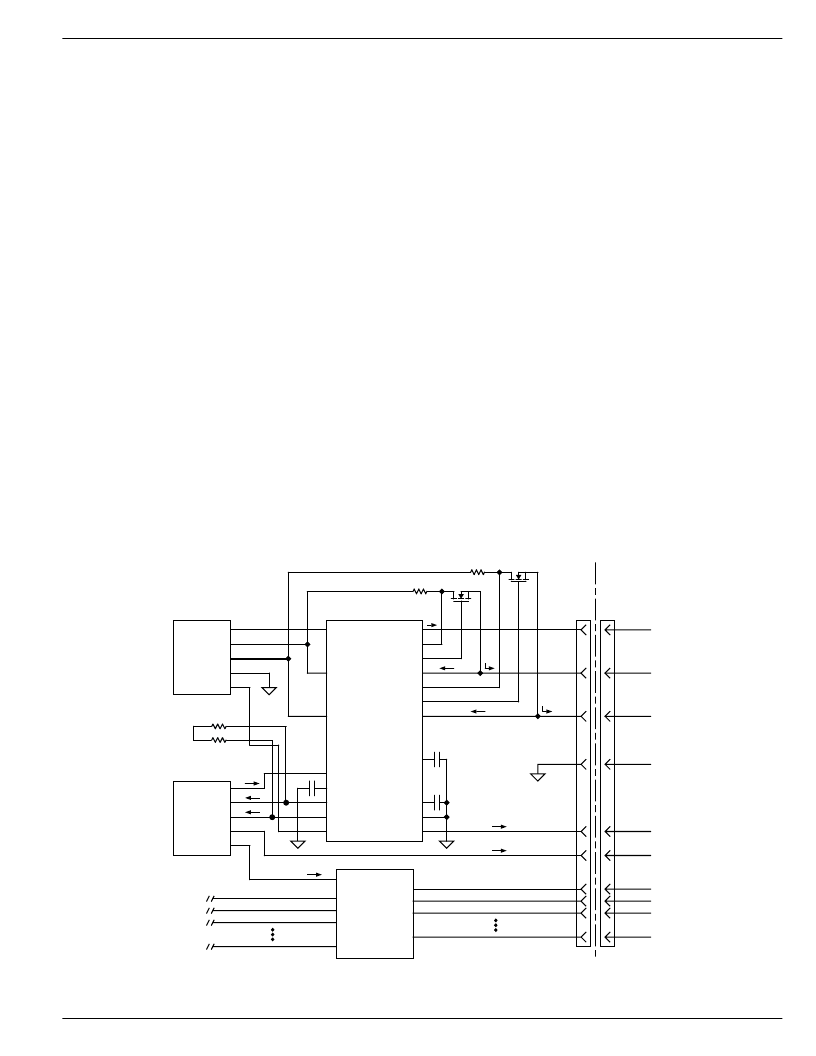
12VOUT
5VSENSE
5VGATE
5VOUT
3VGATE
3VOUT
VPCHG
/POR
12VIN
/FAULT
CSTART
GND
/LPCIRST
5VIN
3VIN
/PCIRST
/ON
CSLEW
/EPWDGD
/PWDGD
M12VIN
MIC2580
3VSENSE
CRST
IRF7413
IRF7413
3.3V
5V
12V
M12VOUT
+12V
+5V
+3.3V
GND
–
12V
Power
Supply
/CIRST
BUS EN
–
12V
/CIRST
D
/CIRST
–
12V /100mA
12V/500mA
5V/5A
3.3V/7.6A
10m
10m
PCI Hot-Plug
Controller
Bus
Switch
D
GND
A
P
D0
D1
D2
D0
D1
D2
+5V
Dn
Dn
Figure 5. Hot-Plug PCI Application
相關(guān)PDF資料 |
PDF描述 |
|---|---|
| MIC2588 | Single-Channel, Negative High-Voltage Hot Swap Power Controllers |
| MIC2588-1BM | Single-Channel, Negative High-Voltage Hot Swap Power Controllers |
| MIC2588-2BM | Single-Channel, Negative High-Voltage Hot Swap Power Controllers |
| MIC2594 | Single-Channel, Negative High-Voltage Hot Swap Power Controllers |
| MIC2594-1BM | Single-Channel, Negative High-Voltage Hot Swap Power Controllers |
相關(guān)代理商/技術(shù)參數(shù) |
參數(shù)描述 |
|---|---|
| MIC2580-1.0BTS | 制造商:Micrel Inc 功能描述:Hot Swap Controller 24-Pin TSSOP 制造商:Rochester Electronics LLC 功能描述:- Bulk |
| MIC2580-1.0BTSTR | 制造商:Rochester Electronics LLC 功能描述:- Tape and Reel |
| MIC2580-1.6BTS | 制造商:Rochester Electronics LLC 功能描述:- Bulk |
| MIC2580A-1.0BTS | 功能描述:IC CTRLR HOTSWAP PCI PWR 24TSSOP RoHS:否 類(lèi)別:集成電路 (IC) >> PMIC - 熱交換 系列:- 產(chǎn)品培訓(xùn)模塊:Obsolescence Mitigation Program 標(biāo)準(zhǔn)包裝:100 系列:- 類(lèi)型:熱插拔開(kāi)關(guān) 應(yīng)用:通用 內(nèi)部開(kāi)關(guān):是 電流限制:可調(diào) 電源電壓:9 V ~ 13.2 V 工作溫度:-40°C ~ 150°C 安裝類(lèi)型:表面貼裝 封裝/外殼:10-WFDFN 裸露焊盤(pán) 供應(yīng)商設(shè)備封裝:10-TDFN-EP(3x3) 包裝:管件 |
| MIC2580A-1.0BTS TR | 功能描述:IC CTRLR PCI HOT SWAP 24-TSSOP RoHS:否 類(lèi)別:集成電路 (IC) >> PMIC - 熱交換 系列:- 產(chǎn)品培訓(xùn)模塊:Obsolescence Mitigation Program 標(biāo)準(zhǔn)包裝:100 系列:- 類(lèi)型:熱插拔開(kāi)關(guān) 應(yīng)用:通用 內(nèi)部開(kāi)關(guān):是 電流限制:可調(diào) 電源電壓:9 V ~ 13.2 V 工作溫度:-40°C ~ 150°C 安裝類(lèi)型:表面貼裝 封裝/外殼:10-WFDFN 裸露焊盤(pán) 供應(yīng)商設(shè)備封裝:10-TDFN-EP(3x3) 包裝:管件 |
發(fā)布緊急采購(gòu),3分鐘左右您將得到回復(fù)。