- 您現(xiàn)在的位置:買賣IC網(wǎng) > PDF目錄383604 > MIC2186BM (MICREL INC) Low Voltage PWM Control IC PDF資料下載
參數(shù)資料
| 型號(hào): | MIC2186BM |
| 廠商: | MICREL INC |
| 元件分類: | 穩(wěn)壓器 |
| 英文描述: | Low Voltage PWM Control IC |
| 中文描述: | SWITCHING CONTROLLER, 440 kHz SWITCHING FREQ-MAX, PDSO16 |
| 封裝: | SOP-16 |
| 文件頁數(shù): | 10/16頁 |
| 文件大?。?/td> | 162K |
| 代理商: | MIC2186BM |
MIC2186
Micrel
MIC2186
10
July 2002
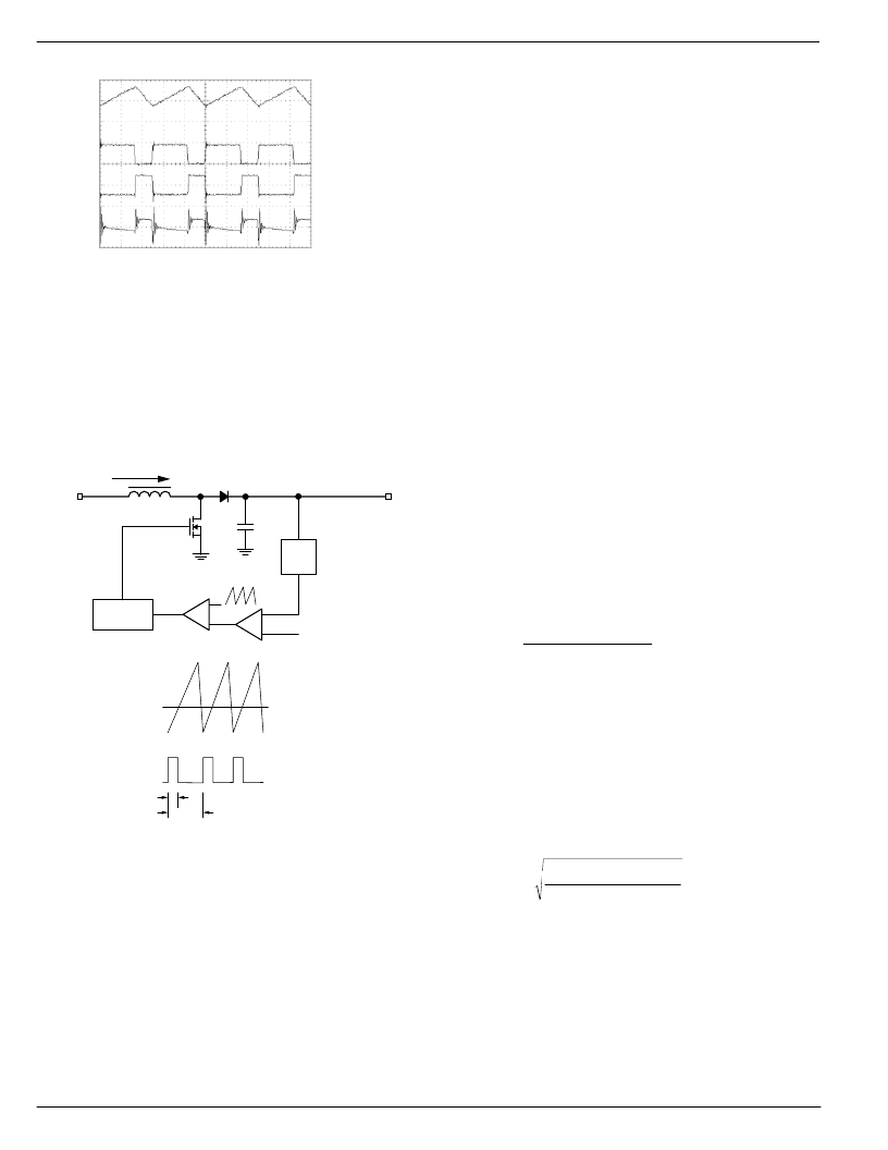
Conditions:
V
IN
= 3V
V
= 9V
I
O
= 0.6A
MOSFET gate
drive @ 10V/div
Switch Node Voltage
(MOSFET Drain)
@10V/div
VOUT Ripple Voltage
@50mV/div
Inductor Current @
1A/div
PWM Mode Waveforms
TIME (1
μ
s/div)
Figure 5 - PWM mode waveforms
The MIC2186 uses current mode control to improve output
regulation and simplify compensation of the control loop.
Current mode control senses both the output voltage (outer
loop) and the inductor current (inner loop). It uses the inductor
current and output voltage to determine the duty cycle (D) of
the buck converter. Sampling the inductor current effectively
removes the inductor from the control loop, which simplifies
compensation. A simplified current mode control diagram is
shown in Figure 6.
I_inductor
T
ON
T
PER
V
COMP
I_inductor
I_inductor
Gate Driver
I_inductor
Voltage
Divider
V
REF
V
IN
Gate Drive at OutN
Figure 6: PWM Control Loop
A block diagram of the MIC2186 PWM current mode control
loop is shown in Figure 1. The inductor current is sensed by
measuring the voltage across a resistor, Rsense. The current
sense amplifier buffers and amplifies this signal. A ramp is
added to this signal to provide slope compensation, which is
required in current mode control to prevent unstable opera-
tion at duty cycles greater than 50%.
A transconductance amplifier is used as an error amplifier,
which compares an attenuated output voltage with a refer-
ence voltage. The output of the error amplifier is compared to
the current sense waveform in the PWM block. When the
current signal rises above the error voltage, the comparator
turns off the low side drive. The error signal is brought out to
the COMP pin (pin 4) to provide access to the output of the
error amplifier. This allows the use of external components to
stabilize the voltage loop.
Current Sensing and Overcurrent Protection
The inductor current is sensed during the switch on time by
a current sense resistor located between the source of the
MOSFET and ground (Rsense in Figure 1). Exceeding the
current limit threshold will immediately terminate the gate
drive of the N-channel MOSFET, Q1. This forces the Q1 to
operate at a reduced duty cycle, which lowers the output
voltage.
In a boost converter, the overcurrent limit will not
protect the power supply or load during a severe
overcurrent condition or short circuit condition.
If the
output is short-circuited to ground, current will flow from the
input, through the inductor and output diode to ground. Only
the impedance of the source and components limits the
current.
The mode of operation (continuous or discontinuous), the
minimum input voltage, maximum output power and the
minimum value of the current limit threshold determine the
value of the current sense resistor. Discontinuous mode is
where all the energy in the inductor is delivered to the output
at each switching cycle. Continuous mode of operation
occurs when current always flows in the inductor, during both
the low-side MOSFET on and off times. The equations below
will help to determine the current sense resistor value for
each operating mode.
The critical value of output current in a boost converter is
calculated below. The operating mode is discontinuous if the
output current is below this value and is continuous if above
this value.
(
×
×
I
V
V
V
2
fs L
V
CRIT
IN
2
O
IN
O
2
=
×
)
×
η
where:
η
is the efficiency of the boost converter
Vin is the minimum input voltage
L is the value of the boost inductor
Fs is the switching frequency
Vo is the output voltage
Maximum Peak Current in Discontinuous Mode:
The peak inductor current is:
(
I
2 I
V
L
V
fs
IND(pk)
O
O
×
IN
=
×
×
)
η
where:
Io is the maximum output current
Vo is the output voltage
Vin is the minimum input voltage
L is the value of the boost inductor
fs is the switching frequency
η
is the efficiency of the boost converter
The maximum value of current sense resistor is:
相關(guān)PDF資料 |
PDF描述 |
|---|---|
| MIC2196YM | 400kHz SO-8 Boost Control IC |
| MIC2196 | 400kHz SO-8 Boost Control IC |
| MIC2196BM | 400kHz SO-8 Boost Control IC |
| MIC2202 | HIGH EFFICIENCY 2MHZ SYNCHRONOUS BUCK CONVERTER 1UP STABLE PWM REGULATOR |
| MIC2202BML | HIGH EFFICIENCY 2MHZ SYNCHRONOUS BUCK CONVERTER 1UP STABLE PWM REGULATOR |
相關(guān)代理商/技術(shù)參數(shù) |
參數(shù)描述 |
|---|---|
| MIC2186BM TR | 功能描述:IC REG CTRLR BST FLYBK CM 16SOIC RoHS:否 類別:集成電路 (IC) >> PMIC - 穩(wěn)壓器 - DC DC 切換控制器 系列:- 標(biāo)準(zhǔn)包裝:4,000 系列:- PWM 型:電壓模式 輸出數(shù):1 頻率 - 最大:1.5MHz 占空比:66.7% 電源電壓:4.75 V ~ 5.25 V 降壓:是 升壓:無 回掃:無 反相:無 倍增器:無 除法器:無 Cuk:無 隔離:無 工作溫度:-40°C ~ 85°C 封裝/外殼:40-VFQFN 裸露焊盤 包裝:帶卷 (TR) |
| MIC2186BQS | 功能描述:IC REG CTRLR BST FLYBK CM 16QSOP RoHS:否 類別:集成電路 (IC) >> PMIC - 穩(wěn)壓器 - DC DC 切換控制器 系列:- 標(biāo)準(zhǔn)包裝:4,000 系列:- PWM 型:電壓模式 輸出數(shù):1 頻率 - 最大:1.5MHz 占空比:66.7% 電源電壓:4.75 V ~ 5.25 V 降壓:是 升壓:無 回掃:無 反相:無 倍增器:無 除法器:無 Cuk:無 隔離:無 工作溫度:-40°C ~ 85°C 封裝/外殼:40-VFQFN 裸露焊盤 包裝:帶卷 (TR) |
| MIC2186BQS TR | 功能描述:IC REG CTRLR BST FLYBK CM 16QSOP RoHS:否 類別:集成電路 (IC) >> PMIC - 穩(wěn)壓器 - DC DC 切換控制器 系列:- 標(biāo)準(zhǔn)包裝:4,000 系列:- PWM 型:電壓模式 輸出數(shù):1 頻率 - 最大:1.5MHz 占空比:66.7% 電源電壓:4.75 V ~ 5.25 V 降壓:是 升壓:無 回掃:無 反相:無 倍增器:無 除法器:無 Cuk:無 隔離:無 工作溫度:-40°C ~ 85°C 封裝/外殼:40-VFQFN 裸露焊盤 包裝:帶卷 (TR) |
| MIC2186YM | 功能描述:DC/DC 開關(guān)控制器 SO-16 Low Vin Synchronous Buck PWM Control IC (Lead Free) RoHS:否 制造商:Texas Instruments 輸入電壓:6 V to 100 V 開關(guān)頻率: 輸出電壓:1.215 V to 80 V 輸出電流:3.5 A 輸出端數(shù)量:1 最大工作溫度:+ 125 C 安裝風(fēng)格: 封裝 / 箱體:CPAK |
| MIC2186YM TR | 功能描述:DC/DC 開關(guān)控制器 SO-16 Low Vin Synchronous Buck PWM Control IC (Lead Free) RoHS:否 制造商:Texas Instruments 輸入電壓:6 V to 100 V 開關(guān)頻率: 輸出電壓:1.215 V to 80 V 輸出電流:3.5 A 輸出端數(shù)量:1 最大工作溫度:+ 125 C 安裝風(fēng)格: 封裝 / 箱體:CPAK |
發(fā)布緊急采購,3分鐘左右您將得到回復(fù)。