- 您現(xiàn)在的位置:買賣IC網(wǎng) > PDF目錄383602 > MH89770S (Mitel Networks Corporation) Ultraframer DS3/E3/DS2/E2/DS1/E1/DS0 PDF資料下載
參數(shù)資料
| 型號: | MH89770S |
| 廠商: | Mitel Networks Corporation |
| 元件分類: | 通信及網(wǎng)絡(luò) |
| 英文描述: | Ultraframer DS3/E3/DS2/E2/DS1/E1/DS0 |
| 中文描述: | Ultraframer DS3/E3/DS2/E2/DS1/E1/DS0 |
| 文件頁數(shù): | 23/36頁 |
| 文件大?。?/td> | 836K |
| 代理商: | MH89770S |
第1頁第2頁第3頁第4頁第5頁第6頁第7頁第8頁第9頁第10頁第11頁第12頁第13頁第14頁第15頁第16頁第17頁第18頁第19頁第20頁第21頁第22頁當(dāng)前第23頁第24頁第25頁第26頁第27頁第28頁第29頁第30頁第31頁第32頁第33頁第34頁第35頁第36頁
4-147
Preliminary Information
MH89770
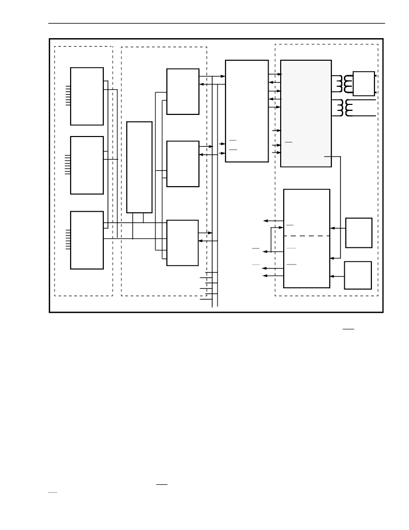
Figure 16 - Digital Multiplex Interface (DMI)
Asynchronous
Interface
Protocol Converter
Switch Matrix
T1 Interface
R
S
2
3
2
ACIA
A
0
-A
7
D
0
-D
7
A
0
-A
7
A
0
-A
7
D
0
-D
7
D
0
-D
7
ACIA
ACIA
Micro
68008
MT8952
MT8952
MT8952
D
0
-D
7
A
0
-A
7
D
0
-D
7
A
0
-A
7
D
0
-D
7
A
0
-A
7
MT8941
DPLL #1
STo3
STi2
STo2
STi1
STo1
C4i
F0i
STo0
STi0
F0i
F0i
C1.5i
C4i
C2i
C2i
C1.5i
OUTA
OUTB
RxT
RxR
E8Ko
CSTi1
CSTo
CSTi0
DSTo
DSTi
izer
Equal-
CVb
F0i
C12i
C4b
C20
F0b
C8Kb
DPLL #2
12.352
MHz
Osc.
MHz
Osc.
16.384
R
S
2
3
2
R
S
2
3
2
MT8980
MH89770
The control block only interfaces with the switch
matrix. Besides routing channels and signalling
through to the proper destination, the switch matrix
must also supply the Master Control Words, and
monitor the Master Status Words for each MH89770.
The clock generation block supplies the ST-BUS
clocks and the T1 transmit clocks that are
synchronized to one of the T1 trunks. All of the
extracted 8 kHz outputs are NANDed together before
they are input to PLL #2 of the MT8941.
Phase-locked Loop #2 of the MT8941, will generate
ST-BUS clock signals for the MH89770s and the
MT8980s that are synchronized with the chosen T1
line. The E8Ko of all of the other MH89770s can be
tristated from the Master Control Word, which allows
the system controller to select any one of 128 T1
lines to act as the synchronization source. By
connecting the frame pulse output, F0o, of PLL #2 to
F0i of PLL # 1, the MT8941 will generate the T1
transmit clock that is phase-locked to F0o, which in
turn is phase-locked to the master synchronization
signal, E8Ko. If all of the T1 trunks are from the
network any short term differences in the received
data rate will be absorbed by the elastic buffer in the
MH89770.
6. Digital Multiplex Interface (DMI)
Figure 16 illustrates an implementation of the Digital
Multiplex Interface (DMI) specification, which defines
a computer to PBX interface. This interface can
convert 300 baud to 64 kbaud asynchronous or
synchronous data channels to T1 format with clear
channel capabilities and common channel signalling.
Figure 16 is broken down into four functional blocks
which are the asynchronous interface (ACIAs), the
protocol converter (micro and MT8952s), the switch
matrix (MT8980), and the T1 interface (MH89770).
相關(guān)PDF資料 |
PDF描述 |
|---|---|
| MH89790B | Ultraframer DS3/E3/DS2/E2/DS1/E1/DS0 |
| MH89790BN | Ultraframer DS3/E3/DS2/E2/DS1/E1/DS0 |
| MH89790BS | Ultraframer DS3/E3/DS2/E2/DS1/E1/DS0 |
| MH89791 | CEPT PCM 30 Transmit Equalizer Advance Information |
| MH89792-1 | E1 Transceiver Preliminary Information |
相關(guān)代理商/技術(shù)參數(shù) |
參數(shù)描述 |
|---|---|
| MH89790B | 制造商:MITEL 功能描述: 制造商:ZARLNK 功能描述: |
| MH89790BN | 制造商:MITEL 制造商全稱:Mitel Networks Corporation 功能描述:ST-BUS⑩ FAMILY CEPT PCM 30/CRC-4 Framer & Interface Preliminary Information |
| MH89790BS | 制造商:MITEL 制造商全稱:Mitel Networks Corporation 功能描述:ST-BUS⑩ FAMILY CEPT PCM 30/CRC-4 Framer & Interface Preliminary Information |
| MH89791 | 制造商:MITEL 制造商全稱:Mitel Networks Corporation 功能描述:CEPT PCM 30 Transmit Equalizer Advance Information |
| MH89792 | 制造商:MITEL 制造商全稱:Mitel Networks Corporation 功能描述:E1 Transceiver Preliminary Information |
發(fā)布緊急采購,3分鐘左右您將得到回復(fù)。