- 您現(xiàn)在的位置:買賣IC網(wǎng) > PDF目錄358174 > MG75J1ZS40 75 A, 600 V, N-CHANNEL IGBT PDF資料下載
參數(shù)資料
| 型號: | MG75J1ZS40 |
| 元件分類: | IGBT 晶體管 |
| 英文描述: | 75 A, 600 V, N-CHANNEL IGBT |
| 封裝: | 2-94D2A, 5 PIN |
| 文件頁數(shù): | 1/5頁 |
| 文件大小: | 386K |
| 代理商: | MG75J1ZS40 |
MG75J1ZS40
2001-02-22 1/5
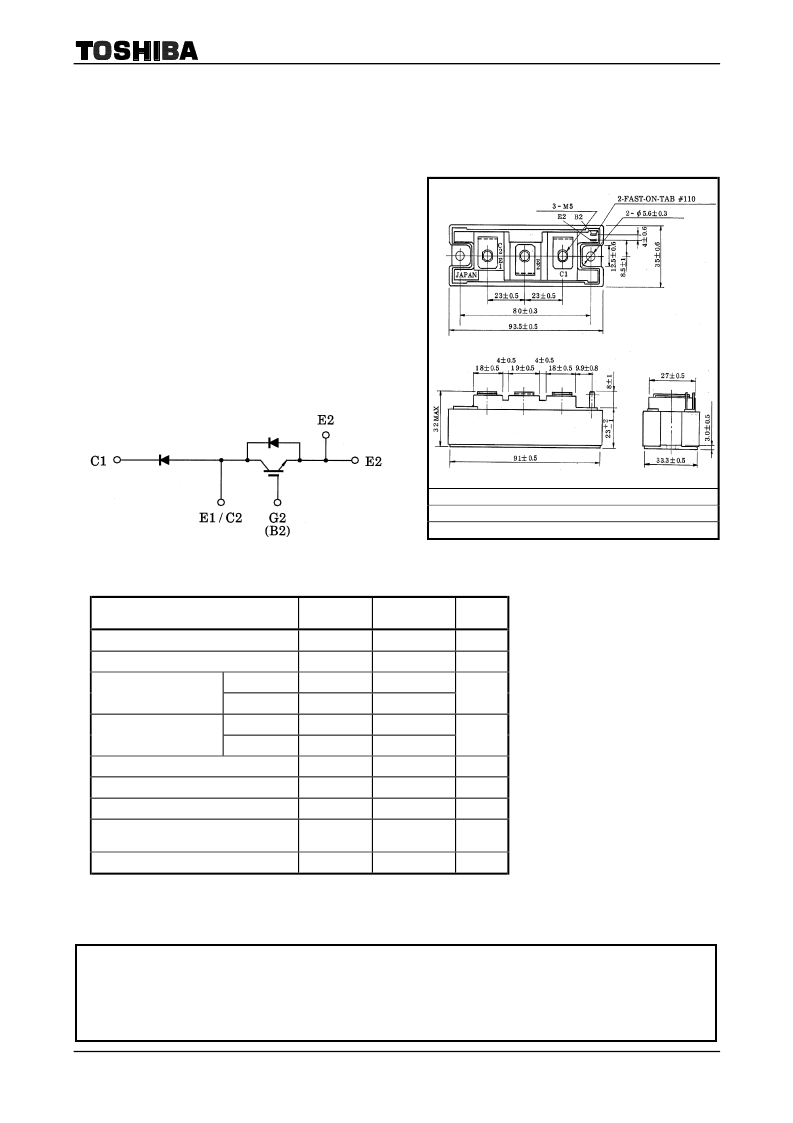
TOSHIBA GTR Module Silicon N Channel IGBT
MG75J1ZS40
High Power Switching Applications
Motor Control Applications
z
High input impedance
z
High speed
: t
f
= 0.35μs (Max)
t
rr
= 0.15μs (Max)
z
Low saturation voltage : V
CE
(sat)
= 3.5V (Max)
z
Enhancement-mode
z
The electrodes are isolated from case.
Equivalent Circuit
Maximum Ratings
(Ta = 25°C)
Characteristic
Symbol
Rating
Unit
Collector-emitter voltage
V
CES
600
V
Gate-emitter voltage
V
GES
±20
V
DC
I
C
75
Collector current
1ms
I
CP
150
A
DC
I
F
75
Forword current
1ms
I
FM
150
A
Collector power dissipation (Tc = 25°C)
P
C
350
W
Junction temperature
T
j
150
°C
Storage temperature range
T
stg
40 ~ 125
°C
Isolation voltage
V
Isol
2500
(AC, 1 minute)
V
Screw torque (Terminal / mounting)
―
3 / 3
N·m
JEDEC
EIAJ
TOSHIBA
Weight: 202g
―
―
2-94D2A
Unit: mm
TOSHIBA is continually working to improve the quality and reliability of its products. Nevertheless, semiconductor devices in general
can malfunction or fail due to their inherent electrical sensitivity and vulnerability to physical stress. It is the responsibility of the
buyer, when utilizing TOSHIBA products, to comply with the standards of safety in making a safe design for the entire system, and
to avoid situations in which a malfunction or failure of such TOSHIBA products could cause loss of human life, bodily injury or
damage to property.
In developing your designs, please ensure that TOSHIBA products are used within specified operating ranges as set forth in the
most recent TOSHIBA products specifications. Also, please keep in mind the precautions and conditions set forth in the “Handling
Guide for Semiconductor Devices,” or “TOSHIBA Semiconductor Reliability Handbook” etc..
000707EAA2
相關PDF資料 |
PDF描述 |
|---|---|
| MGB61D | SINGLE COLOR LED, GREEN, 5 mm |
| MGB81C | SINGLE COLOR LED, GREEN, 4.88 mm |
| MGF0917A | L & S BAND GaAs FET [ SMD non ? matched ] |
| MGF1102 | C BAND, GaAs, N-CHANNEL, RF SMALL SIGNAL, JFET |
| MGF4409-6-0-909 | 9 CONTACT(S), FEMALE, RIGHT ANGLE TWO PART BOARD CONNECTOR, SOLDER, SOCKET |
相關代理商/技術參數(shù) |
參數(shù)描述 |
|---|---|
| MG75J1ZS50 | 制造商:TOSHIBA 制造商全稱:Toshiba Semiconductor 功能描述:N CHANNEL IGBT (HIGH POWER SWITCHING, MOTOR CONTROL APPLICATIONS) |
| MG75J2YS45 | 制造商:n/a 功能描述:IGBT Module |
| MG75J2YS50 | 制造商:n/a 功能描述:IGBT Module |
| MG75J6ES50 | 制造商:n/a 功能描述:IGBT Module 制造商:Toshiba America Electronic Components 功能描述: |
| MG75M2YK1 | 制造商:未知廠家 制造商全稱:未知廠家 功能描述:TRANSISTOR MODULES |
發(fā)布緊急采購,3分鐘左右您將得到回復。