- 您現(xiàn)在的位置:買賣IC網(wǎng) > PDF目錄359163 > MG-5100SA (愛普生(中國(guó))有限公司) Multi-Output Crystal Oscillator(多輸出晶體振蕩器) PDF資料下載
參數(shù)資料
| 型號(hào): | MG-5100SA |
| 廠商: | 愛普生(中國(guó))有限公司 |
| 英文描述: | Multi-Output Crystal Oscillator(多輸出晶體振蕩器) |
| 中文描述: | 多輸出晶體振蕩器(多輸出晶體振蕩器) |
| 文件頁(yè)數(shù): | 1/1頁(yè) |
| 文件大小: | 118K |
| 代理商: | MG-5100SA |
52
Crystal oscillator
Specifications (characteristics)
Twice at Under +260
°
C within 10 s
±
100 x 10
-6
100 mA Max.
65 mA Max.
-55
°
C
to +100
°
C
-20
°
C
to +70
°
C
V
DD
-GND
V
DD
T
STG
T
OPR
T
SOL
f / f
O
l
OP
t
W
/ t
V
OH
V
OL
C
L
15 pF Max.
80 %V
DD
Min.
20 %V
DD
Max.
40 % to 60 %
V
DD
-0.4 V Min.
0.4 V Max.
25 pF Max.
V
IH
V
IL
t
TLH
t
THL
-0.3 V to +7.0 V
5.0
±
0.5 V
3.3
±
0.3 V
fo
76.9 kHz to 100.0 MHz.
1
76.9 kHz to 80.0000 MHz.
1
4.0 ns Max.
450 ps Max.
500 ps Max.
500 ps Max.
70 ms Max.
5.0 ns Max.
t
j
t
skw
t
OSC
±
5 x 10
-6
/year Max.
±
20 x 10
-6
Max.
f
a
S.R.
6
5
7
2
1
13
9
4
10
3
12
GND
TIN
V
DD2
V
DD1
OE
CLKA
CLKB
CLKC
CLKD
CPUCLK
XBUF
S0
S1
S2
11
8
14
Terminal
Pin No.
Function
Power supply (3.3V or 5.0V)
GND
Do not connect anything
Output control (
”
H
”
:Enable,
”
L
”
:Weak pull-down)
Clock output ports.
Reference clock output
Select pin 0 for clock output
Select pin 1 for clock output
Select pin 2 for clock output
External dimensions
Terminal condition
(Unit: mm)
7
±
0
5
10.1
±
0.2
1
2
3
4
5
6
7
14 13 12 11 10 9
8
3
3
±
0
0.6
0.35
1.27
0
0
0
°
1
°
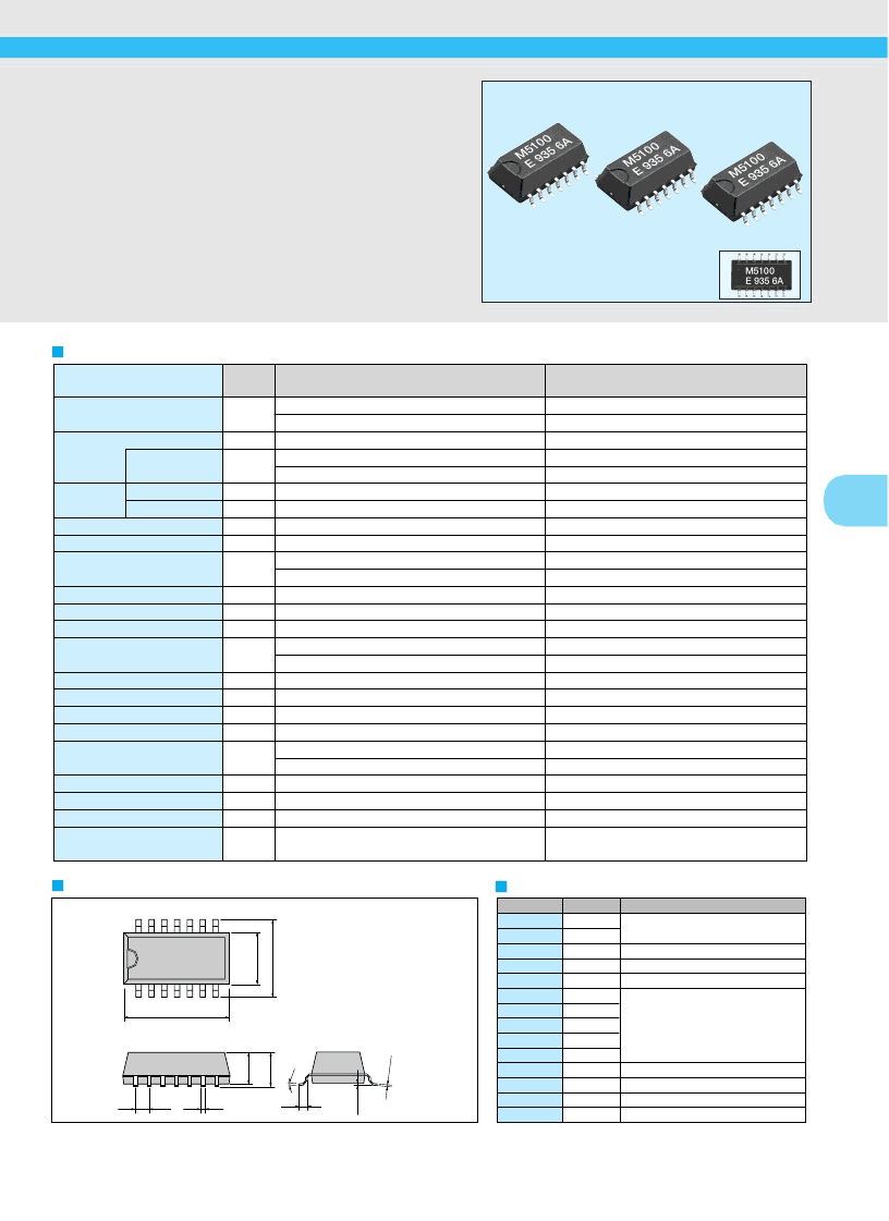
935 6A
M5100 AB
E
MULTI-OUTPUT CRYSTAL OSCILLATOR
MG-5100SA
High density mounting type SMD, SOP-14pin package.
Cylindrical AT crystal unit built-in, thus assuring high reliability.
Three-PLL circuits allowed to be programmable for output
frequency.
Available to choose output in 8 frequencies by select pin for
CPU CLK.
Item
Symbol
Specifications
Remarks
V
DD
=5.0
V ±0.5 V
V
DD
=3.3
V ±0.3 V
V
DD
=5.0
V ±0.5 V
V
DD
=3.3
V ±0.3 V
50 % V
DD
I
OH
= -4.0 mA
I
OL
= 4.0 mA
V
DD
=5.0
V ±0.5 V
V
DD
=3.3
V ±0.3 V
20
%
→
80
%
V
DD
80
%
→
20
%
V
DD
Cycle to Cycle jitter
Peak to Peak Jitter
250 ps Typ.
Ta= +25
°
C, V
DD
=3.3
V or 5.5V
Three drops on a hard board from 750 mm or excitation test
with 29400 m/s
2
x 0.3 ms x 1/2sine wave in 3 directions
Actual size
Output frequency range
Power source
voltage
Temperature
range
Soldering condition
Frequency stability
Current consumption
Duty
“
H
”
output voltage 1
“
L
”
output voltage 1
condition (fan out)
“
H
”
input voltage 1
“
L
”
input voltage 1
Output rise time
Output fall time
Jitter
Skew
Oscillation start up time
Aging
Shock resistance
Storage temperature
Operating temperature
Max. supply voltage
Operating voltage
1 Please contact us for inquiries about usable frequencies.
相關(guān)PDF資料 |
PDF描述 |
|---|---|
| MG-7010SA | Crystal oscillator |
| MG-7010SA | Selectable-Output PLL Oscillator(輸出可選鎖相環(huán)振蕩器) |
| MG100Q2YS50A | Network Hub; Approval Categories:Cisco CDP Compatibility; Data Rate:100Mbps RoHS Compliant: Yes |
| MG10Q6ES50A | N CHANNEL IGBT (HIGH PWER SWITCHING, MOTOR CONTROL APPLICATIONS) |
| MG10Q6ES51A | CAP 68UF 35V 20% TANT SMD-7361-38 TR-7 |
相關(guān)代理商/技術(shù)參數(shù) |
參數(shù)描述 |
|---|---|
| MG51T | 制造商:MICRO-ELECTRONICS 制造商全稱:Micro Electronics 功能描述:GREEN LED LAMPS |
| MG51W | 制造商:MICRO-ELECTRONICS 制造商全稱:Micro Electronics 功能描述:GREEN LED LAMPS |
| MG5223 | 制造商:E2VINC 功能描述: |
| MG5244 | 制造商:E2VINC 功能描述: |
| MG533-00067 | 制造商:TE Connectivity 功能描述:BEND PINS OF HEA1035 |
發(fā)布緊急采購(gòu),3分鐘左右您將得到回復(fù)。