- 您現(xiàn)在的位置:買賣IC網(wǎng) > PDF目錄371100 > MF6256M-02BJxx (Mitsubishi Electric Corporation) 2.5 Flash Drive PDF資料下載
參數(shù)資料
| 型號(hào): | MF6256M-02BJxx |
| 廠商: | Mitsubishi Electric Corporation |
| 英文描述: | 2.5 Flash Drive |
| 中文描述: | 2.5閃存盤 |
| 文件頁(yè)數(shù): | 4/18頁(yè) |
| 文件大小: | 145K |
| 代理商: | MF6256M-02BJXX |
第1頁(yè)第2頁(yè)第3頁(yè)當(dāng)前第4頁(yè)第5頁(yè)第6頁(yè)第7頁(yè)第8頁(yè)第9頁(yè)第10頁(yè)第11頁(yè)第12頁(yè)第13頁(yè)第14頁(yè)第15頁(yè)第16頁(yè)第17頁(yè)第18頁(yè)
MITSUBISHI STORAGE CARD
Preliminary
MF6XXXX-02BJXX series
FLASH DRIVES
Oct.2000
. Rev. 0.3
MITSUBISHI
ELECTRIC
4/18
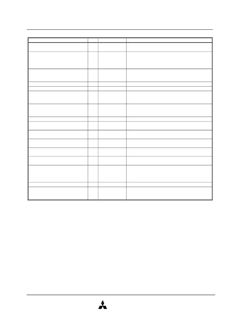
Signal Description
Signal Name
I/O
I
Pin No.
Description
Address bus[DA2-DA0]
36, 33, 35
Signals DA2-DA0 are address bus. DA2 is the MSB
and DA0 is the LSB.
Signals DD15-DD0 are data bus.
Data bus[D15-D0]
I/O
18, 16, 14, 12,
10, 8, 6, 4, 3, 5,
7, 9, 11, 13, 15,
17
37, 38
Chip select[CS0#, CS1#]
I
CS0# is used to select the Command Block
Registers. CS1# is used to select the Control Block
Registers.
DIOR# is used to read data from the Drive’s I/O space.
DIOW# is used to write data to the Drive’s I/O space.
This signal shall be used by the host in response to
DMARQ to either acknowledge that data has been
accepted, or that data is available.
This signal, used for DMA data transfer between host
and drive, shall be asserted by the drive when it is
ready to transfer data to or from the host.
This signal is active high interrupt request to the host.
This output signal is asserted when the I/O port
address is capable of 16-bit access.
This signal is the DISK Active/Slave Present signal in
the Master/Slave handshake protocol.
This input pin is the active low hardware reset from the
host.
This signal is asserted to delay completion of the
memory or I/O access cycle.
This signal is the Pass Diagnostic signal in the
Master/Slave handshake protocol.
This signal is used to configure this Drive as a Master
or a Slave. When this signal is grounded, this Drive is
configured as a Master. When this signal is Open, this
Drive is configure as a Slave.
5V power.
Ground.
Drive I/O read[DIOR#]
Drive I/O write[DIOW#]
DMA acknowledge[DMACK#]
I
I
I
25
23
29
DMA request[DMARQ]
O
21
Drive interrupt[INTRQ]
Drive 16-bit I/O[IOCS16#]
O
O
31
32
Drive active/drive1 present[DASP#]
I/O
39
Drive reset[RESET#]
I
1
I/O channel ready[IORDY]
O
27
Passed diagnostics[PDIAG#]
I/O
34
Cable select[CSEL]
I
28
V
DD
GND
-
-
41, 42
2, 19, 22, 24,
26, 30, 40, 43,
44
相關(guān)PDF資料 |
PDF描述 |
|---|---|
| MF601G2-02BJxx | 2.5 Flash Drive |
| MF6640M-02BJxx | 2.5 Flash Drive |
| MF6512M-02BJxx | Composite Camera Cable; Number of Conductors:7; Conductor Size AWG:22; No. Strands x Strand Size:7 x 30; Jacket Material:Polyvinylchloride (PVC); Number of Pairs:3; Coaxial RG/U Type:59; Conductor Material:Copper RoHS Compliant: Yes |
| MF84M1-GMCAVXX | 8/16-bit Data Bus Flash Memory Card |
| MF832M-GMCAVXX | 8/16-bit Data Bus Flash Memory Card |
相關(guān)代理商/技術(shù)參數(shù) |
參數(shù)描述 |
|---|---|
| MF6300-04 | 制造商:KAYNAR (ALCOA) 功能描述: |
| MF6300-06 | 制造商:KAYNAR (ALCOA) 功能描述: |
| MF6301-04 | 制造商:KAYNAR (ALCOA) 功能描述: |
| MF630106 | 制造商:n/a 功能描述:Ships in 2 days |
| MF6301-06 | 制造商:KAYNAR (ALCOA) 功能描述: |
發(fā)布緊急采購(gòu),3分鐘左右您將得到回復(fù)。