- 您現(xiàn)在的位置:買賣IC網(wǎng) > PDF目錄382324 > MEA75-12 (IXYS Corporation) Fast Recovery Epitaxial Diode (FRED) Module PDF資料下載
參數(shù)資料
| 型號(hào): | MEA75-12 |
| 廠商: | IXYS Corporation |
| 英文描述: | Fast Recovery Epitaxial Diode (FRED) Module |
| 中文描述: | 快速恢復(fù)外延二極管(弗雷德)模塊 |
| 文件頁(yè)數(shù): | 1/2頁(yè) |
| 文件大小: | 91K |
| 代理商: | MEA75-12 |
2000 IXYS All rights reserved
D6 - 5
150
600
200
250
300
22
33
90
-40...+150
-40...+125
110
280
3000
3600
12.7
9.6
50
0.550
0.450
Data according to IEC 60747
IXYS reserves the right to change limits, test conditions and dimensions
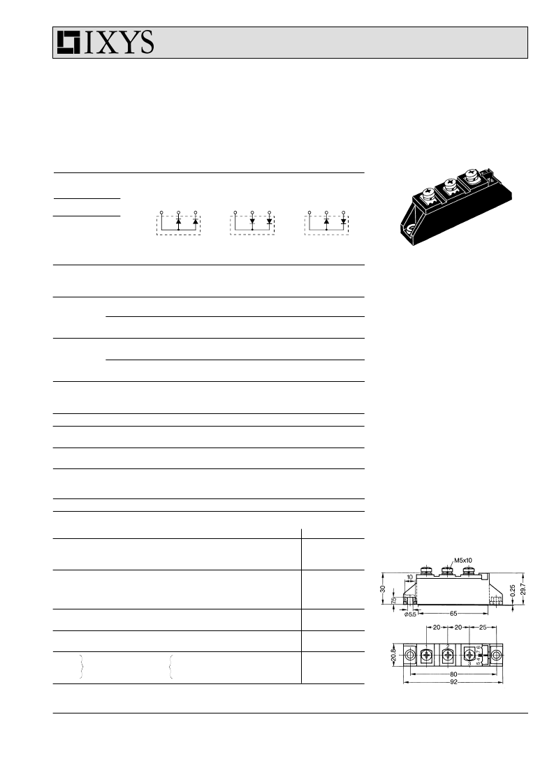
Dimensions in mm (1 mm = 0.0394")
Features
G
International standard package
with DCB ceramic base plate
G
Planar passivated chips
G
Short recovery time
G
Low switching losses
G
Soft recovery behaviour
G
Isolation voltage 3600 V~
G
UL registered E 72873
Applications
G
Antiparallel diode for high frequency
switching devices
G
Free wheeling diode in converters
and motor control circuits
G
Inductive heating and melting
G
Uninterruptible power supplies (UPS)
G
Ultrasonic cleaners and welders
Advantages
G
High reliability circuit operation
G
Low voltage peaks for reduced
protection circuits
G
Low noise switching
G
Low losses
Preliminary data
75
75
107
75
TBD
1200
1300
1080
1170
7200
7100
5800
5700
2.50-4/22-35
2.50-4/22-35
100
1.85
2.17
2.58
2.64
300
2
0.5
34
1.48
3.65
1
2
3
1
2
3
1
2
3
V
RSM
V
V
RRM
V
Type
MEA75-12 DA
MEK 75-12 DA
MEE 75-12 DA
1200
1200
Symbol
Test Conditions
°
C
T
case
=
°
C; rectangular, d = 0.5
t
P
< 10
μ
s; rep. rating, pulse width limited by T
VJM
T
VJ
= 45
°
C;
t = 10 ms (50 Hz), sine
t = 8.3 ms (60 Hz), sine
T
VJ
= 150
°
C; t = 10 ms (50 Hz), sine
t = 8.3 ms (60 Hz), sine
T
VJ
= 45
°
C;
t = 10 ms (50 Hz), sine
t = 8.3 ms (60 Hz), sine
T
VJ
= 150
°
C; t = 10 ms (50 Hz), sine
t = 8.3 ms (60 Hz), sine
Maximum Ratings
I
FRMS
I
FAV
I
FRM
I
FSM
T
case
=
A
A
A
A
A
A
A
I
2
t
A
2
s
A
2
s
A
2
s
A
2
s
°
C
°
C
°
C
T
VJ
T
stg
T
Hmax
P
tot
V
ISOL
T
case
= 25
°
C
50/60 Hz, RMS t = 1 min
I
ISOL
≤
1 mA
Mounting torque (M5)
Terminal connection torque (M5)
W
V~
V~
t = 1 s
M
d
Nm/lb.in.
Nm/lb.in.
d
S
d
A
a
Creep distance on surface
Strike distance through air
Maximum allowable acceleration
mm
mm
m/s
2
Weight
g
Symbol
Test Conditions
Characteristic Values (per diode)
typ.
max.
I
R
T
VJ
= 25
°
C
T
VJ
= 25
°
C
T
VJ
= 125
°
C
I
F
= A;
V
R
= V
V
R
= 0.8 V
RRM
V
R
= 0.8 V
RRM
T
VJ
=125
°
C
T
VJ
= 25
°
C
T
VJ
=125
°
C
T
VJ
= 25
°
C
mA
mA
mA
V
F
V
V
V
V
I
F
= A;
V
T0
r
T
R
thJH
R
thJC
t
rr
I
RM
For power-loss calculations only
V
m
K/W
K/W
DC current
DC current
I
F
= A
V
R
= V
-di/dt = A/
μ
s
T
VJ
= 100
°
C
T
VJ
= 25
°
C
T
VJ
= 100
°
C
ns
A
A
Fast Recovery
Epitaxial Diode
(FRED) Module
MEA 75-12 DA
MEK 75-12 DA
MEE 75-12 DA
V
RRM
= 1200 V
I
FAV
= 75 A
t
rr
= 250 ns
TO-240 AA
1
2
3
相關(guān)PDF資料 |
PDF描述 |
|---|---|
| MEA75-12DA | Fast Recovery Epitaxial Diode (FRED) Module |
| MEK150-04DA | Fast Recovery Epitaxial Diode (FRED) Module |
| MEO500-06DA | Fast Recovery Epitaxial Diode (FRED) Module(正向電流514A的快速恢復(fù)外延型二極管模塊) |
| MEO550-02DA | Fast Recovery Epitaxial Diode (FRED) Module |
| MERA-7456 | Dual Matched MMIC Amplifiers |
相關(guān)代理商/技術(shù)參數(shù) |
參數(shù)描述 |
|---|---|
| MEA75-12DA | 功能描述:分立半導(dǎo)體模塊 150 Amps 1200V RoHS:否 制造商:Infineon Technologies 產(chǎn)品:Thyristor Power Modules 類型:Phase Controls 安裝風(fēng)格:Screw 封裝 / 箱體:DT61 封裝: |
| MEA8020T10R0T | 制造商:TDK 功能描述: |
| MEA8020T75R0T | 制造商:TDK 功能描述: |
| MEA825KF | 制造商:TRW Inc 功能描述: |
| MEA95-06DA | 功能描述:分立半導(dǎo)體模塊 190 Amps 600V RoHS:否 制造商:Infineon Technologies 產(chǎn)品:Thyristor Power Modules 類型:Phase Controls 安裝風(fēng)格:Screw 封裝 / 箱體:DT61 封裝: |
發(fā)布緊急采購(gòu),3分鐘左右您將得到回復(fù)。