- 您現(xiàn)在的位置:買賣IC網(wǎng) > PDF目錄299476 > MDR5100-14000 (SPECTRUM CONTROL INC) MECHANICAL TUNED DRO, 14000 MHz PDF資料下載
參數(shù)資料
| 型號: | MDR5100-14000 |
| 廠商: | SPECTRUM CONTROL INC |
| 元件分類: | XO, clock |
| 英文描述: | MECHANICAL TUNED DRO, 14000 MHz |
| 文件頁數(shù): | 1/2頁 |
| 文件大?。?/td> | 321K |
| 代理商: | MDR5100-14000 |
CHARACTERISTIC
TYPICAL
MIN/MAX
Ta= 25 C
Ta = -20 C to +65 C
Frequency (GHz)2
14
Supply Power DC6
+12
mA
265
275
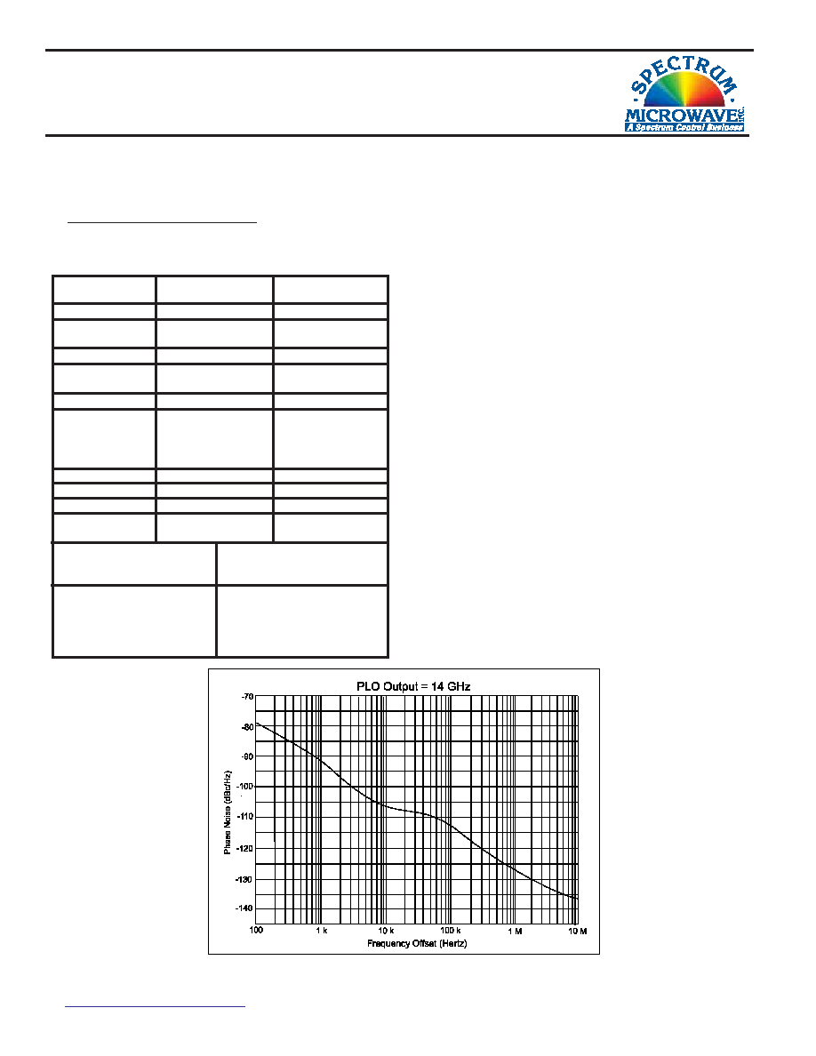
PHASE LOCKED OSCILLATOR
MODEL MDR5100-14000 (14 GHz)
VSWR
1.5
2.0
Phase Noise (dB)5
-92 dBc/Hz @ 1 KHz
-107 dBc/Hz @ 10 KHz
-113 dBc/Hz @ 100 KHz
-127 dBc/Hz @ 1 MHz
Spurious (dBc)
-80
-70
Variation Over
Temperature (dBm)
+/- 0.75
+/- 1
Output Power (dBm)4
+13
+12
Specifications1
Features
!
! Low Phase Noise: -113 dBc/Hz @ 100 kHz
!
! Low Spurious: -80 dBc Typical
!
! Internal Reference Design
!
! Environmental Screening Available
Harmonics (dBc)
-20
-15
Spectrum Microwave, Inc.
2707 Black Lake Place Phila, Pa. 19154
www.SpectrumMicrowave.com
PH: 215-464-4000 FAX: 215-464-4001
Rev.
10/30/08
Description
Spectrum Microwave’s Series MDR5100 Phase
Locked Oscillators use a Dielectric Resonator in
the resonant circuit. The circuit is lightly loaded to
obtain the lowest phase noise possible.
The resonator is epoxied to a printed circuit
board and well grounded to minimize modulation
sidebands during shock and vibration.
Buffer amplifiers are used to provide isolation
from load VSWRs; Regulators filter noise on
the DC input voltage.
External reference models are also available.
A lock indicator circuit is provided to signal an
out-of-lock condition.
Notes:
1. Specifications labeled “min.” or “max.” are guaranteed in a 50 Ohm system over the
specified temperature range.
2. Output frequency must be specified, and it is an integer multiple of the internal crystal
reference frequency.
3. Mechanical tuning of PLO in unlocked mode.
4. Higher output power is available.
5. Phase Noise at offsets <100 kHz is dependent on external reference and can be
approximated as follows: Phase Noise (dB) = 20log(N) +3 dB above the external reference
phase noise, where N = multiple of reference.
6. Other input voltages are available.
7. Actual or impending loss of lock.
8. Package must be verified by Spectrum Microwave.
Lock Indicator
TTL (High=Locked)
TTL (Low=Unlocked)
Mechanical Tuning
Bandwidth (MHz)3
+/- 20
+/- 20 Min.
Phase Voltage
Set to (nom.)
+5.0 VDC
Lock Range (min.)
+2 to +9 VDC
Phase-Lock Alarm
Transistor Collector (NPN)
Locked
Open Vc = 30 VDC max.
Unlocked7
Saturated to Ground
Vce = +0.5 VDC max.
Ic = 50 mA max.
相關(guān)PDF資料 |
PDF描述 |
|---|---|
| MDR5100-17000 | MECHANICAL TUNED DRO, 17000 MHz |
| MDR5100-4000 | MECHANICAL TUNED DRO, 4000 MHz |
| MDR6100-15000 | MECHANICAL TUNED DRO, 15000 MHz |
| MDRM18I9524/C270 | MAGNETIC FIELD SENSOR-MAGNETORESISTIVE, 4-20mA, CYLINDRICAL |
| MDRM18I9524 | LINEAR OPTICAL POSITION ENCODER |
相關(guān)代理商/技術(shù)參數(shù) |
參數(shù)描述 |
|---|---|
| MDR5100-15000 | 制造商:SPECTRUM 制造商全稱:Spectrum Microwave, Inc. 功能描述:PHASE LOCKED OSCILLATOR |
| MDR5100-16000 | 制造商:SPECTRUM 制造商全稱:Spectrum Microwave, Inc. 功能描述:PHASE LOCKED OSCILLATOR |
| MDR5100-17000 | 制造商:SPECTRUM 制造商全稱:Spectrum Microwave, Inc. 功能描述:PHASE LOCKED OSCILLATOR |
| MDR5100-18000 | 制造商:SPECTRUM 制造商全稱:Spectrum Microwave, Inc. 功能描述:PHASE LOCKED OSCILLATOR |
| MDR5100-19000 | 制造商:SPECTRUM 制造商全稱:Spectrum Microwave, Inc. 功能描述:PHASE LOCKED OSCILLATOR |
發(fā)布緊急采購,3分鐘左右您將得到回復。