- 您現(xiàn)在的位置:買賣IC網(wǎng) > PDF目錄9316 > MCP4461T-502E/ML (Microchip Technology)IC DGTL POT 257TAPS 5K 20QFN PDF資料下載
參數(shù)資料
| 型號(hào): | MCP4461T-502E/ML |
| 廠商: | Microchip Technology |
| 文件頁數(shù): | 93/100頁 |
| 文件大小: | 0K |
| 描述: | IC DGTL POT 257TAPS 5K 20QFN |
| 標(biāo)準(zhǔn)包裝: | 3,300 |
| 接片: | 257 |
| 電阻(歐姆): | 5k |
| 電路數(shù): | 4 |
| 溫度系數(shù): | 標(biāo)準(zhǔn)值 150 ppm/°C |
| 存儲(chǔ)器類型: | 非易失 |
| 接口: | I²C(設(shè)備位址) |
| 電源電壓: | 2.7 V ~ 5.5 V |
| 工作溫度: | -40°C ~ 125°C |
| 安裝類型: | 表面貼裝 |
| 封裝/外殼: | 20-VFQFN 裸露焊盤 |
| 供應(yīng)商設(shè)備封裝: | 20-QFN 裸露焊盤(4x4) |
| 包裝: | 帶卷 (TR) |
第1頁第2頁第3頁第4頁第5頁第6頁第7頁第8頁第9頁第10頁第11頁第12頁第13頁第14頁第15頁第16頁第17頁第18頁第19頁第20頁第21頁第22頁第23頁第24頁第25頁第26頁第27頁第28頁第29頁第30頁第31頁第32頁第33頁第34頁第35頁第36頁第37頁第38頁第39頁第40頁第41頁第42頁第43頁第44頁第45頁第46頁第47頁第48頁第49頁第50頁第51頁第52頁第53頁第54頁第55頁第56頁第57頁第58頁第59頁第60頁第61頁第62頁第63頁第64頁第65頁第66頁第67頁第68頁第69頁第70頁第71頁第72頁第73頁第74頁第75頁第76頁第77頁第78頁第79頁第80頁第81頁第82頁第83頁第84頁第85頁第86頁第87頁第88頁第89頁第90頁第91頁第92頁當(dāng)前第93頁第94頁第95頁第96頁第97頁第98頁第99頁第100頁
MCP444X/446X
DS22265A-page 92
2010 Microchip Technology Inc.
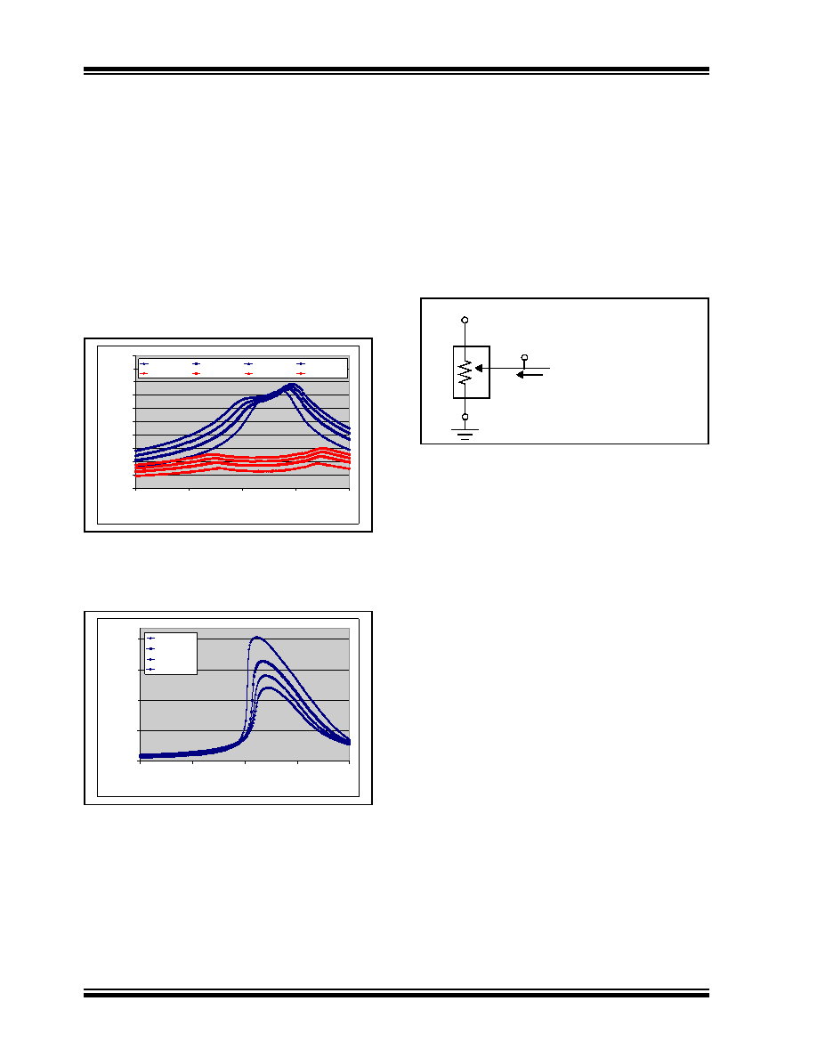
Figure B-3 and Figure B-4 show the wiper resistance
for VDD voltages of 5.5, 3.0, 1.8 Volts. These graphs
show that as the resistor ladder wiper node voltage
(VWCn) approaches the VDD/2 voltage, the wiper
resistance increases. These graphs also show the
different resistance characteristics of the NMOS and
PMOS transistors that make up the wiper switch. This
is demonstrated by the wiper code resistance curve,
which does not mirror itself around the mid-scale code
(wiper code = 128).
So why are the RW graphs showing the maximum
resistance at about mid-scale (wiper code = 128) and
the RBW graphs showing the issue at code 160?
This requires understanding low-voltage transistor
characteristics as well as how the data was measured.
FIGURE B-3:
Wiper Resistance (RW) vs.
Wiper Code and Temperature
(VDD = 5.5V, IW = 900 A; VDD = 3.0V,
IW = 480 A).
FIGURE B-4:
Wiper Resistance (RW) vs.
Wiper Code and Temperature
(VDD = 1.8V, IW = 260 A).
The method in which the data was collected is
important to understand. Figure B-5 shows the
technique that was used to measure the RBW and RW
resistance. In this technique, Terminal A is floating and
Terminal B is connected to ground. A fixed current is
then forced into the wiper (IW) and the corresponding
wiper voltage (VW) is measured. Forcing a known
current through RBW (IW) and then measuring the
voltage difference between the wiper (VW) and
Terminal A (V), the wiper resistance (RW) can be
change the wiper voltage (VW). This may affect the
device’s wiper resistance (RW).
FIGURE B-5:
RBW and RW Measurement.
Figure B-6 shows a block diagram of the resistor
network where the RAB resistor is a series of 256 RS
resistors. These resistors are polysilicon devices. Each
wiper switch is an analog switch made up of an NMOS
and PMOS transistor. A more detailed figure of the
wiper switch is shown in Figure B-7. The wiper
resistance is influenced by the voltage on the wiper
switches nodes (VG, VW and VWCn). Temperature also
influences the characteristics of the wiper switch, see
The NMOS transistor and PMOS transistor have
different characteristics. These characteristics, as well
as the wiper switch node voltages, determine the RW
resistance at each wiper code. The variation of each
wiper switch’s characteristics in the resistor network is
greater then the variation of the RS resistors.
The voltage on the resistor network node (VWCn) is
dependent upon the wiper code selected and the
voltages applied to VA, VB and VW. The wiper switch VG
voltage to VW or VWCn voltage determines how strongly
the transistor is turned on. When the transistor is
weakly turned on, the wiper resistance RW will be high.
When the transistor is strongly turned on, the wiper
resistance (RW) will be in the typical range.
20
40
60
80
100
120
140
160
180
200
220
0
64
128
192
256
Wiper Code
Resistance
()
-40C @ 3.0V
+25C @ 3.0V
+85C @ 3.0V
+125C @ 3.0V
-40C @5.5V
+25C @ 5.5V
+85C @ 5.5V
+125C @ 5.5V
20
520
1020
1520
2020
0
64
128
192
256
Wiper Code
Resistance
()
-40C @ 1.8V
+25C @ 1.8V
+85C @ 1.8V
+125C @ 1.8V
A
B
W
IW
VW
floating
RBW = VW/IW
VA
VB
RW = (VW-VA)/IW
相關(guān)PDF資料 |
PDF描述 |
|---|---|
| MCP4461T-503E/ML | IC DGTL POT 257TAPS 50K 20QFN |
| VE-B1F-MW-B1 | CONVERTER MOD DC/DC 72V 100W |
| VE-B1B-MV | CONVERTER MOD DC/DC 95V 150W |
| VI-BNV-MY-F1 | CONVERTER MOD DC/DC 5.8V 50W |
| M83723/74R14078 | CONN RCPT 7POS JAM NUT W/PINS |
相關(guān)代理商/技術(shù)參數(shù) |
參數(shù)描述 |
|---|---|
| MCP4461T-503E/ML | 功能描述:數(shù)字電位計(jì) IC 50k I2C Qd Ch 8bit Nonvolatile memory RoHS:否 制造商:Maxim Integrated 電阻:200 Ohms 溫度系數(shù):35 PPM / C 容差:25 % POT 數(shù)量:Dual 每 POT 分接頭:256 弧刷存儲(chǔ)器:Volatile 緩沖刷: 數(shù)字接口:Serial (3-Wire, SPI) 描述/功能:Dual Volatile Low Voltage Linear Taper Digital Potentiometer 工作電源電壓:1.7 V to 5.5 V 電源電流:27 uA 最大工作溫度:+ 125 C 安裝風(fēng)格:SMD/SMT 封裝 / 箱體:TQFN-16 封裝:Reel |
| MCP4461T-503E/ST | 功能描述:數(shù)字電位計(jì) IC 50k I2C Qd Ch 8bit Nonvolatile memory RoHS:否 制造商:Maxim Integrated 電阻:200 Ohms 溫度系數(shù):35 PPM / C 容差:25 % POT 數(shù)量:Dual 每 POT 分接頭:256 弧刷存儲(chǔ)器:Volatile 緩沖刷: 數(shù)字接口:Serial (3-Wire, SPI) 描述/功能:Dual Volatile Low Voltage Linear Taper Digital Potentiometer 工作電源電壓:1.7 V to 5.5 V 電源電流:27 uA 最大工作溫度:+ 125 C 安裝風(fēng)格:SMD/SMT 封裝 / 箱體:TQFN-16 封裝:Reel |
| MCP4462-103E/ST | 功能描述:數(shù)字電位計(jì) IC 10k I2C Quad Ch 8bit Nonvolatile Memory RoHS:否 制造商:Maxim Integrated 電阻:200 Ohms 溫度系數(shù):35 PPM / C 容差:25 % POT 數(shù)量:Dual 每 POT 分接頭:256 弧刷存儲(chǔ)器:Volatile 緩沖刷: 數(shù)字接口:Serial (3-Wire, SPI) 描述/功能:Dual Volatile Low Voltage Linear Taper Digital Potentiometer 工作電源電壓:1.7 V to 5.5 V 電源電流:27 uA 最大工作溫度:+ 125 C 安裝風(fēng)格:SMD/SMT 封裝 / 箱體:TQFN-16 封裝:Reel |
| MCP4462-103E/ST | 制造商:Microchip Technology Inc 功能描述:; End To End Resistance:10kohm; Track Ta 制造商:Microchip Technology Inc 功能描述:IC, DIG POT, 10kohm, 257STEPS, QUAD, TSSOP-14 |
| MCP4462-104E/ST | 功能描述:數(shù)字電位計(jì) IC 100k I2C Quad Ch 8bt Nonvolatile Memory RoHS:否 制造商:Maxim Integrated 電阻:200 Ohms 溫度系數(shù):35 PPM / C 容差:25 % POT 數(shù)量:Dual 每 POT 分接頭:256 弧刷存儲(chǔ)器:Volatile 緩沖刷: 數(shù)字接口:Serial (3-Wire, SPI) 描述/功能:Dual Volatile Low Voltage Linear Taper Digital Potentiometer 工作電源電壓:1.7 V to 5.5 V 電源電流:27 uA 最大工作溫度:+ 125 C 安裝風(fēng)格:SMD/SMT 封裝 / 箱體:TQFN-16 封裝:Reel |
發(fā)布緊急采購,3分鐘左右您將得到回復(fù)。