- 您現(xiàn)在的位置:買賣IC網(wǎng) > PDF目錄383585 > MCP131X (Microchip Technology Inc.) Voltage Supervisor PDF資料下載
參數(shù)資料
| 型號: | MCP131X |
| 廠商: | Microchip Technology Inc. |
| 英文描述: | Voltage Supervisor |
| 中文描述: | 電壓監(jiān)控 |
| 文件頁數(shù): | 21/44頁 |
| 文件大小: | 924K |
| 代理商: | MCP131X |
第1頁第2頁第3頁第4頁第5頁第6頁第7頁第8頁第9頁第10頁第11頁第12頁第13頁第14頁第15頁第16頁第17頁第18頁第19頁第20頁當(dāng)前第21頁第22頁第23頁第24頁第25頁第26頁第27頁第28頁第29頁第30頁第31頁第32頁第33頁第34頁第35頁第36頁第37頁第38頁第39頁第40頁第41頁第42頁第43頁第44頁
2005 Microchip Technology Inc.
DS21985A-page 21
MCP131X/2X
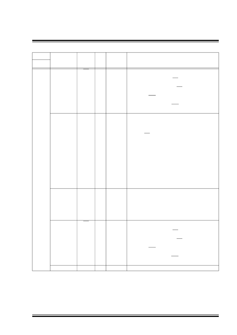
3
MCP1316,
MCP1316M,
MCP1317,
MCP1320
MR
I
ST
Manual Reset input for a Reset switch.
This input allows a push button switch to be directly con-
nected to the MCP131X/2X MR pin, which can then be
used to force a system Reset. This input filters (ignores)
noise pulses that occur on the MR pin.
L = Switch is depressed (shorted to ground). This forces
the RST/RST pins Active.
H = Switch is open (internal pull-up resistor pulls signal
high). State of the RST/RST pins determined by
other system conditions.
Reset Output (active-high)
Goes active (High) if one of these conditions occurs:
1.
If V
DD
falls below the selected Reset voltage
threshold.
2.
If the MR pin is forced low.
3.
If the WDI pin does not detect an edge transition
within the minimum selected time out period.
4.
During power-up.
MCP1318,
MCP1318M,
MCP1319,
MCP1319M,
MCP1321,
MCP1322
RST
O
Push-Pull
V
DD
Falling:
H = V
DD
< V
TRIP
L = V
DD
> V
TRIP
V
DD
Rising:
H = V
DD
< V
TRIP
+ V
HYS
L = V
DD
> V
TRIP
+ V
HYS
Watchdog Timer Input
The WDT period is specified at the time of device order.
The Standard WDT period is 1.6s typical.
An edge transition on the WDI pin resets the Watchdog
Timer counter (no time out). A Falling Edge is required to
start the WDT Timer.
4
MCP1316,
MCP1316M,
MCP1317,
MCP1318,
MCP1318M,
MCP1320,
MCP1321
MCP1319,
MCP1319M,
MCP1322
WDI
I
ST
MR
I
ST
Manual Reset input for a Reset switch.
This input allows a push button switch to be directly con-
nected to the MCP131X/2X MR pin, which can then be
used to force a system Reset. This input filters (ignores)
noise pulses that occur on the MR pin.
L = Switch is depressed (shorted to ground). This forces
the RST/RST pins Active.
H = Switch is open (internal pull-up resistor pulls signal
high). State of the RST/RST pins determined by
other system conditions.
The positive supply for the device.
5
All
V
DD
—
P
TABLE 3-1:
PIN FUNCTION TABLE (CONTINUED)
Pin No.
Device
Symbol
Pin
Type
Buffer/
Driver
Type
Function
SOT23-5
Note 1:
Open-Drain output with internal pull-up resistor.
相關(guān)PDF資料 |
PDF描述 |
|---|---|
| MCP1320 | Voltage Supervisor |
| MCP1320T | Voltage Supervisor |
| MCP1321 | Voltage Supervisor |
| MCP1321T | Voltage Supervisor |
| MCP1322 | Voltage Supervisor |
相關(guān)代理商/技術(shù)參數(shù) |
參數(shù)描述 |
|---|---|
| MCP131X_12 | 制造商:MICROCHIP 制造商全稱:Microchip Technology 功能描述:Voltage Supervisor |
| MCP1320 | 制造商:MICROCHIP 制造商全稱:Microchip Technology 功能描述:Voltage Supervisor |
| MCP1320T | 制造商:MICROCHIP 制造商全稱:Microchip Technology 功能描述:Voltage Supervisor |
| MCP1320T-25LE | 制造商:MICROCHIP 制造商全稱:Microchip Technology 功能描述:Voltage Supervisor |
| MCP1320T-25LE/OT | 制造商:Microchip Technology Inc 功能描述: |
發(fā)布緊急采購,3分鐘左右您將得到回復(fù)。