- 您現(xiàn)在的位置:買賣IC網(wǎng) > PDF目錄384729 > MC74LVX244DWR2G (ON SEMICONDUCTOR) Octal Bus Buffer With 5V−Tolerant Inputs PDF資料下載
參數(shù)資料
| 型號: | MC74LVX244DWR2G |
| 廠商: | ON SEMICONDUCTOR |
| 元件分類: | 通用總線功能 |
| 英文描述: | Octal Bus Buffer With 5V−Tolerant Inputs |
| 中文描述: | LV/LV-A/LVX/H SERIES, DUAL 4-BIT DRIVER, TRUE OUTPUT, PDSO20 |
| 封裝: | LEAD FREE, SOIC-20 |
| 文件頁數(shù): | 4/8頁 |
| 文件大小: | 105K |
| 代理商: | MC74LVX244DWR2G |
MC74LVX244
http://onsemi.com
4
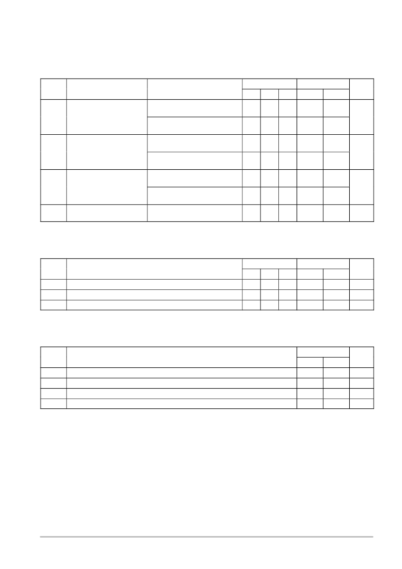
The specification applies to any outputs switching in the same direction, either HIGHtoLOW (t
OSHL
) or LOWtoHIGH (t
OSLH
); parameter
guaranteed by design.
Symbol
7.2
10.6
Parameter
Test Conditions
Min
8.6
Typ
1.0
t
High and Low Level
t
PHL
R
= 1k
Input to Output
V
= 3.3
0.3V
C
L
= 50pF
8.0
9.6
4.7
7.1
1.0
11.6
16.0
8.5
17.0
C
= 15pF
L
t
PLZ
,
PHZ
PZL
V
CC
= 2.7V
L
Output Enable Time to
CC
L
C
= 50pF
12.3
1.0
19.0
1.5
20.0
16.5
(Note 1)
R
L
= 1k
C
L
= 50pF
1.5
1.0
14.0
ns
C
L
= 50pF
R
= 1k
V
CC
= 3.3
±
0.3V
CC
L
13.0
t
OSLH
C
L
= 50pF
PD
is defined as the value of the internal equivalent capacitance which is calculated from the operating current consumption without load.
Average operating current can be obtained by the equation: I
CC(OPR
)
= C
PD
V
CC
f
in
+ I
CC
/8 (per bit). C
PD
is used to determine the noload
dynamic power consumption; P
D
= C
PD
V
CC2
f
in
+ I
CC
V
CC
.
A
A
out
PD
pF
NOISE CHARACTERISTICS
(Input t
r
= t
f
= 3.0ns, C
L
= 50pF, V
CC
= 3.3V, Measured in SOIC Package)
T
A
= 25
°
C
Symbol
Characteristic
Typ
Max
Unit
V
OLP
Quiet Output Maximum Dynamic V
OL
0.5
0.8
V
V
OLV
Quiet Output Minimum Dynamic V
OL
0.5
0.8
V
V
IHD
Minimum High Level Dynamic Input Voltage
2.0
V
V
ILD
Maximum Low Level Dynamic Input Voltage
0.8
V
相關(guān)PDF資料 |
PDF描述 |
|---|---|
| MC74LVX244MEL | Octal Bus Buffer With 5V−Tolerant Inputs |
| MC74LVX245DTR2 | Octal Bus Transceiver With 5 V−Tolerant Inputs |
| MC74LVX245DWR2 | Octal Bus Transceiver With 5 V−Tolerant Inputs |
| MC74LVX245DWR2G | Octal Bus Transceiver With 5 V−Tolerant Inputs |
| MC74LVX245MEL | Octal Bus Transceiver With 5 V−Tolerant Inputs |
相關(guān)代理商/技術(shù)參數(shù) |
參數(shù)描述 |
|---|---|
| MC74LVX244M | 功能描述:緩沖器和線路驅(qū)動器 2-3.6V Octal 3-State RoHS:否 制造商:Micrel 輸入線路數(shù)量:1 輸出線路數(shù)量:2 極性:Non-Inverting 電源電壓-最大:+/- 5.5 V 電源電壓-最小:+/- 2.37 V 最大工作溫度:+ 85 C 安裝風(fēng)格:SMD/SMT 封裝 / 箱體:MSOP-8 封裝:Reel |
| MC74LVX244MEL | 功能描述:緩沖器和線路驅(qū)動器 2-3.6V Octal 3-State RoHS:否 制造商:Micrel 輸入線路數(shù)量:1 輸出線路數(shù)量:2 極性:Non-Inverting 電源電壓-最大:+/- 5.5 V 電源電壓-最小:+/- 2.37 V 最大工作溫度:+ 85 C 安裝風(fēng)格:SMD/SMT 封裝 / 箱體:MSOP-8 封裝:Reel |
| MC74LVX244MELG | 功能描述:緩沖器和線路驅(qū)動器 2-3.6V Octal 3-State Non-Inverting RoHS:否 制造商:Micrel 輸入線路數(shù)量:1 輸出線路數(shù)量:2 極性:Non-Inverting 電源電壓-最大:+/- 5.5 V 電源電壓-最小:+/- 2.37 V 最大工作溫度:+ 85 C 安裝風(fēng)格:SMD/SMT 封裝 / 箱體:MSOP-8 封裝:Reel |
| MC74LVX244MG | 功能描述:緩沖器和線路驅(qū)動器 2-3.6V Octal 3-State Non-Inverting RoHS:否 制造商:Micrel 輸入線路數(shù)量:1 輸出線路數(shù)量:2 極性:Non-Inverting 電源電壓-最大:+/- 5.5 V 電源電壓-最小:+/- 2.37 V 最大工作溫度:+ 85 C 安裝風(fēng)格:SMD/SMT 封裝 / 箱體:MSOP-8 封裝:Reel |
| MC74LVX245DT | 制造商:ON Semiconductor 功能描述:Bus XCVR Single 8-CH 3-ST 20-Pin TSSOP 制造商:Rochester Electronics LLC 功能描述:- Tape and Reel |
發(fā)布緊急采購,3分鐘左右您將得到回復(fù)。