- 您現在的位置:買賣IC網 > PDF目錄382306 > MC44608P75 (ON SEMICONDUCTOR) Few External Components Reliable Flexible GreenLine Very High Voltage PWM Controller PDF資料下載
參數資料
| 型號: | MC44608P75 |
| 廠商: | ON SEMICONDUCTOR |
| 元件分類: | 穩(wěn)壓器 |
| 英文描述: | Few External Components Reliable Flexible GreenLine Very High Voltage PWM Controller |
| 中文描述: | SWITCHING CONTROLLER, 82 kHz SWITCHING FREQ-MAX, PDIP8 |
| 封裝: | PLASTIC, DIP-8 |
| 文件頁數: | 6/16頁 |
| 文件大?。?/td> | 266K |
| 代理商: | MC44608P75 |
MC44608
http://onsemi.com
6
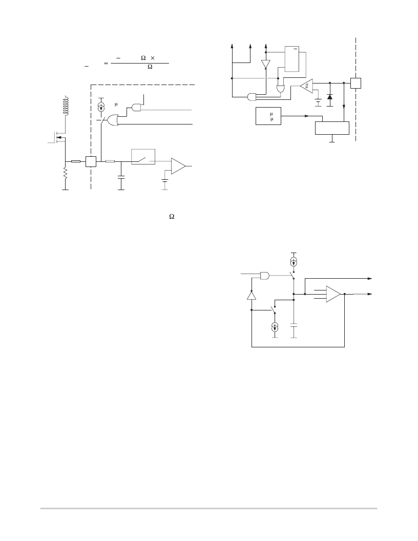
In stand–by mode, this current can be lowered as due to the
activation of a 200
μ
A current source:
1
Ipkmax
stby
(Rcs(k )
Rsense( )
0,2)
(A)
Figure 2. Current Sense
+
–
Switching Phase
1 V
STAND–BY
1
0
&
2
Isense
L.E.B.
Overcurrent
Comparator
OC
200 A
START–UP
Rcs
Rsense
The current sense input consists of a filter (6k , 4pF) and
of a leading edge blanking. Thanks to that, this pin is not
sensitive to the power switch turn on noise and spikes and
practically in most applications, no filtering network is
required to sense the current.
Finally, this pin is used:
– as a protection against over currents (Isense > I)
– as a reduction of the peak current during a Pulsed Mode
switching phase.
The overcurrent propagation delay is reduced by
producing a sharp output turn off (high slew rate). This
results in an abrupt output turn off in the event of an over
current and in the majority of the pulsed mode switching
sequense.
Demagnetization Section
The MC44608 demagnetization detection consists of a
comparator designed to compare the VCC winding voltage
to a reference that is typically equal to 50mV.
This reference is chosen low to increase effectiveness of
the demagnetization detection even during start–up.
A latch is incorporated to turn the demagnetization block
output into a low level as soon as a voltage less than 50 mV
is detected, and to keep it in this state until a new pulse is
generated on the output. This avoids any ringing on the input
signal which may alter the demagnetization detection.
For a higher safety, the demagnetization block output is
also directly connected to the output, which is disabled
during the demagnetization phase.
The demagnetization pin is also used for the quick,
programmable OVP. In fact, the demagnetization input
current is sensed so that the circuit output is latched off when
this current is detected as higher than 120
μ
A.
Figure 3. Demagnetization Block
&
1
DMG
> 24 A
>120 A
Output
Current Mrror
Oscillator Buffer
+
–
Idemag
I
50/20 mV
Demag
R Q
DMG
S
This function can be inhibited by grounding it but in this
case, the quick and programmable OVP is also disabled.
Oscillator
The MC44608 contains a fixed frequency oscillator. It is
built around a fixed value capacitor CT succesively charged
and discharged by two distinct current sources ICH and
IDCH. The window comparator senses the CT voltage value
and activates the sources when the voltage is reaching the
2.4V/4V levels.
Figure 4. Oscillator Block
+
–
froDMG
logic block
4 V
2.4 V
&
Window
comp
OSC
ICH
SDCH
IDCH
SCH
Clock
CT
The complete demagnetization status DMG is used to
inhibit the recharge of the CT capacitor. Thus in case of
incomplete transformer demagnetization the next switching
cycle is postpone until the DMG signal appears. The
oscillator remains at 2.4V corresponding to the sawtooth
valley voltage. In this way the SMPS is working in the so
called SOPS mode (Self Oscillating Power Supply). In that
case the effective switching frequency is variable and no
longer depends on the oscillator timing but on the external
working conditions (Refer to DMG signal in the Figure 5).
相關PDF資料 |
PDF描述 |
|---|---|
| MC44608 | Few External Components Reliable Flexible GreenLine Very High Voltage PWM Controller |
| MC44608P40 | RW-S Series - Econoline Regulated DC-DC Converters; Input Voltage (Vdc): 05V; Output Voltage (Vdc): 09V; Power: 2W; DIP24 Low Profile Miniature Package; 1kVDC Isolation; Feedback Regulated Output; 2:1 Wide Range Voltage Input; Continuous Short Circuit Protection; Less than 7mm Height; SMD Pinning Option; Efficiency to 87% |
| MC44C401 | MTS Stereo Encoder |
| MC44C401FA | MTS Stereo Encoder |
| MC4741C | DIFFERENTIAL INPUT OPERATIONAL AMPLIFIER |
相關代理商/技術參數 |
參數描述 |
|---|---|
| MC44608P75G | 功能描述:電壓模式 PWM 控制器 75KHz High Voltage SMPS PWM RoHS:否 制造商:Texas Instruments 輸出端數量:1 拓撲結構:Buck 輸出電壓:34 V 輸出電流: 開關頻率: 工作電源電壓:4.5 V to 5.5 V 電源電流:600 uA 最大工作溫度:+ 125 C 最小工作溫度:- 40 C 封裝 / 箱體:WSON-8 封裝:Reel |
| MC4466 | 制造商:SHENZHENFREESCALE 制造商全稱:ShenZhen FreesCale Electronics. Co., Ltd 功能描述:N-Channel 30-V (D-S) MOSFET High performance trench technology |
| MC4468 | 制造商:SHENZHENFREESCALE 制造商全稱:ShenZhen FreesCale Electronics. Co., Ltd 功能描述:N-Channel 30-V (D-S) MOSFET High performance trench technology |
| MC44722A | 制造商:MOTOROLA 制造商全稱:Motorola, Inc 功能描述:Advanced Digital Video Encoder |
| MC44722AVFU | 制造商:Rochester Electronics LLC 功能描述: 制造商:Freescale Semiconductor 功能描述: |
發(fā)布緊急采購,3分鐘左右您將得到回復。