- 您現在的位置:買賣IC網 > PDF目錄359731 > MC33742DW (Motorola, Inc.) System Basis Chip (SBC) with Enhanced High-Speed CAN Transceiver PDF資料下載
參數資料
| 型號: | MC33742DW |
| 廠商: | Motorola, Inc. |
| 元件分類: | CAN |
| 英文描述: | System Basis Chip (SBC) with Enhanced High-Speed CAN Transceiver |
| 中文描述: | 系統(tǒng)基礎芯片的增強型(SBC)的高速CAN收發(fā)器 |
| 文件頁數: | 35/52頁 |
| 文件大小: | 1087K |
| 代理商: | MC33742DW |
第1頁第2頁第3頁第4頁第5頁第6頁第7頁第8頁第9頁第10頁第11頁第12頁第13頁第14頁第15頁第16頁第17頁第18頁第19頁第20頁第21頁第22頁第23頁第24頁第25頁第26頁第27頁第28頁第29頁第30頁第31頁第32頁第33頁第34頁當前第35頁第36頁第37頁第38頁第39頁第40頁第41頁第42頁第43頁第44頁第45頁第46頁第47頁第48頁第49頁第50頁第51頁第52頁
MOTOROLA ANALOG INTEGRATED CIRCUIT DEVICE DATA
33742
35
Detection Principle
In the recessive state, if one of the two bus lines is shorted to
GND, V
DD
,
or V
SUP
, then voltage at the other line follows the
shorted line due to bus termination resistance and the high
impedance of the driver. For example, if CANL is shorted to
GND, CANL voltage is zero, and CANH voltage, as measured
by the Hg comparator, is also close to zero.
In the recessive state the failure detection to GND or V
SUP
is
possible. However, it is impossible to distinguish which bus line,
CANL or CANH, is shorted to GND or V
SUP
. In the dominant
state, the complete diagnostic is possible once the driver is
turned on.
CAN Bus Failure Reporting
CANL bus line failures (for example, CANL short to GND) is
reported in the SPI register TIM1/2. CANH bus line (for
example, CANH short to V
SUP
) is reported in the LPC register.
In addition CANF and CAN-UF bits in the CAN register
indicate that a CAN bus failure has been detected.
Non-Identified and Fully Identified Bus Failures
As indicated in
Table 6
, page 34, when the bus is in a
recessive state it is possible to detect an error condition;
however, is it not possible to fully identify which error. This is
called “non-identified” or “under-acquisition” bus failure. If there
is no communication (i.e., bus idle), it is still possible to warn the
MCU that the device has started to detect a bus failure.
In the CAN register, bits D2 and D1 (CAN-F and CAN-UF,
respectively) are used to signal bus failure. Bit D2 reports a bus
failure and bit D1 indicates if the failure is identified or not (bit
D1 is set to 1 if the error is not identified).
When the detection mechanism is complete, the error will be
fully detected and reported in the TIM1/2 and LPC registers and
bit D1 will be reset to 0.
Number of Samples for Proper Failure Detection
The failure detector requires at least one cycle of recessive
and dominant state to properly recognize the bus failure. The
error will be fully detected after five cycles of recessive-
dominant states. As long as the failure detection circuitry has
not detected the same error for five recessive-dominant cycles,
the bit “non-identified failure” (CAN-UF) will be set.
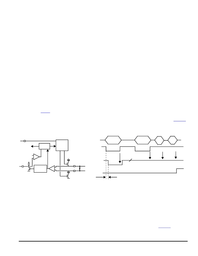
RXD Permanent Recessive Failure
The purpose of this detection mechanism is to diagnose an
external hardware failure at the RXD output terminal and to
ensure that a permanent failure at the RXD terminal does not
disturb network communication.
In the event RXD is shorted to
a permanent high level signal (i.e., 5.0 V), the CAN protocol
module within the MCU cannot receive any incoming message.
Additionally, the CAN protocol module cannot distinguish the
bus idle state and could start communication at any time. To
prevent this, an RXD failure detection, as illustrated in
Figure 22
and explained below, is necessary.
Figure 22. RXD Path and RXD Permanent Recessive Detection Principle
RXD Failure Detection
The 33742 senses the RXD output voltage at each LOW-to-
HIGH transition of the differential receiver. Excluding internal
propagation delay, RXD output should be LOW when the
differential receiver is LOW. In the event RXD is shorted to
5.0 V (e.g., to V
DD
), RXD will be tied to a high level and the RXD
short to 5.0 V can be detected at the next LOW-to-HIGH
transition of the differential receiver. Compete detection
requires three samples.
When the error is detected, the flag is latched and the CAN
driver is disabled. The error is reported through the SPI register
LPC, bit RXPR.
Recovery Condition
The internal recovery is completed by the sampling of a
correct low level at TXD, as illustrated in
Figure 23
, page 36.
As soon as the RXD permanent recessive is detected, the
RXD driver is deactivated and a weak pulldown current source
CANH
CANL
Diff
V
DD
RXD Sense
RXD
Driver
RXD
TXD
TXD
Driver
60
V
DD
Logic
Diag
CANL
CANH
Diff Output
RXD Output
RXD Short to V
DD
Prop Delay
RXD Flag
RXD Flag Latched
2.0 V
Sampling
Sampling
Sampling
Sampling
Note
RXD Flag is neither the RXPR bit in the LPC register nor the
CAN
-
F
bit in the INTR register.
F
Freescale Semiconductor, Inc.
For More Information On This Product,
Go to: www.freescale.com
n
.
相關PDF資料 |
PDF描述 |
|---|---|
| MC33742DWR2 | System Basis Chip (SBC) with Enhanced High-Speed CAN Transceiver |
| MC68HC11A1 | 8-Bit Microcontrollers |
| MC68HC11A1CFN3 | HCMOS Single-Chip Microcontroller |
| MC68HC11A1CFU2 | HCMOS Single-Chip Microcontroller |
| MC68HC11A1CFU3 | HCMOS Single-Chip Microcontroller |
相關代理商/技術參數 |
參數描述 |
|---|---|
| MC33742DWR2 | 功能描述:網絡控制器與處理器 IC SBC-E-HS RoHS:否 制造商:Micrel 產品:Controller Area Network (CAN) 收發(fā)器數量: 數據速率: 電源電流(最大值):595 mA 最大工作溫度:+ 85 C 安裝風格:SMD/SMT 封裝 / 箱體:PBGA-400 封裝:Tray |
| MC33742EP | 功能描述:CAN 接口集成電路 SBC_ECAN_HS RoHS:否 制造商:Texas Instruments 類型:Transceivers 工作電源電壓:5 V 電源電流: 工作溫度范圍:- 40 C to + 85 C 封裝 / 箱體:SOIC-8 封裝:Tube |
| MC33742EPR2 | 功能描述:CAN 接口集成電路 SBC_ECAN_HS RoHS:否 制造商:Texas Instruments 類型:Transceivers 工作電源電壓:5 V 電源電流: 工作溫度范圍:- 40 C to + 85 C 封裝 / 箱體:SOIC-8 封裝:Tube |
| MC33742PEG | 功能描述:CAN 接口集成電路 SBC-E-HS-CAN RoHS:否 制造商:Texas Instruments 類型:Transceivers 工作電源電壓:5 V 電源電流: 工作溫度范圍:- 40 C to + 85 C 封裝 / 箱體:SOIC-8 封裝:Tube |
| MC33742PEGR2 | 功能描述:CAN 接口集成電路 SBC-E-HS-CAN RoHS:否 制造商:Texas Instruments 類型:Transceivers 工作電源電壓:5 V 電源電流: 工作溫度范圍:- 40 C to + 85 C 封裝 / 箱體:SOIC-8 封裝:Tube |
發(fā)布緊急采購,3分鐘左右您將得到回復。