- 您現(xiàn)在的位置:買賣IC網(wǎng) > PDF目錄371029 > MC33348D-3 (MOTOROLA INC) LITHIUM BATTERY PROTECTION CIRCUIT FOR ONE CELL SMART BATTERY PACKS PDF資料下載
參數(shù)資料
| 型號: | MC33348D-3 |
| 廠商: | MOTOROLA INC |
| 元件分類: | 電源管理 |
| 英文描述: | LITHIUM BATTERY PROTECTION CIRCUIT FOR ONE CELL SMART BATTERY PACKS |
| 中文描述: | 1-CHANNEL POWER SUPPLY SUPPORT CKT, PDSO8 |
| 封裝: | PLASTIC, SO-8 |
| 文件頁數(shù): | 8/12頁 |
| 文件大小: | 184K |
| 代理商: | MC33348D-3 |
MC33348
8
MOTOROLA ANALOG IC DEVICE DATA
As the load eventually depletes the battery pack charge,
the Cell Voltage Detector will sense an undervoltage fault
condition when the cell falls below the designed undervoltage
limit. After three consecutive faults are detected, discharge
MOSFET Q2 is turned off, disconnecting the battery pack
from the load. The protection circuit will now enter a low
current sleepmode state. Refer to Figure 6. As a result of the
undervoltage fault, the battery pack is available for charging
only. The typical cutoff thresholds and hysteresis voltage are
shown in Figure 11.
Figure 11. Cutoff and Hysteresis Limits
ááááááááááááááá
á
ááááááááááááááá
ááááááááááááááá
ááááááááááááááá
The undervoltage logic is designed to automatically reset
if less than three consecutive faults appear. This helps to
prevent a premature disconnection of the load during high
current pulses when the battery pack charge is close to
being depleted.
The undervoltage fault is reset by applying charge current
to the battery pack. When the voltage on Pin 3 exceeds Pin 5
by 0.6 V, discharge MOSFET Q2 will turn on. The battery
pack will now be available for charging or discharging.
áá
á
ááá
á
Cutoff
áááá
á
Hysteresis
ááá
á
Cutoff
ááááááááááááááá
8
4
6
5
3
MC33348
Cdly
Rdly
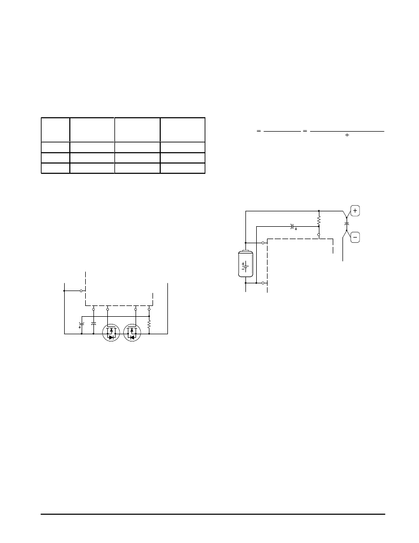
Figure 12. Additional Discharge Current Limit Delay
The discharge current limit shutdown delay time is typically
3.0 ms. This time can be extended with the addition of
components Rdly and Cdly. With an Rdly of 5.1 k and Cdly of 10
μ
F, the current limit shutdown time is extended to 40 ms.
The additional discharge current limit delay circuitry must
not be used if the anticipated open–circuit charger voltage
will exceed 6.0 V. When the charger causes the battery pack
input to exceed 6.0 V, additional current will flow out of Pin 5,
creating a voltage drop across resistor Rdly. This voltage drop
causes the source of MOSFET Q1 to fall below it’s gate,
allowing it to unexpectedly turn back on.
Current Sensing
Discharge current limit protection is internally provided by
the MC33348. As the battery pack discharges, Pins 5 and 3
sense the voltage drop across MOSFETs Q1 and Q2. A
discharge current limit fault is detected if the voltage at Pin 5
is greater than Pin 3 by 400 mV for –1, –3 and –5 suffix
devices, or 200 mV for –2, –4 and –6 suffix devices. The fault
information is stored in a data latch and discharge MOSFET
Q2 is turned off, disconnecting the battery pack from the load.
As a result of the discharge current fault, the battery pack is
available for charging only. The discharge current limit is
given by:
Vth(dschg)
RLim(dschg)
ILim(dschg)
Vth(dschg)
RDS(on)Q1
RDS(on)Q2
The discharge current fault is reset by either disconnecting
the load from the battery pack, or by connecting the battery
pack to the charger. When the voltage on Pin 5 no longer
exceeds Pin 3 by approximately Vth(dschg), the Sense Enable
circuit will turn on discharge MOSFET Q2.
C
10
R
5.1 k
MC33348
Cell
7
1
3
Figure 13. Power Supply Decoupling
In order to guarantee proper discharge current limit
operation when the battery pack output is shorted, power
must be made available to the MC33348. This can be
accomplished by decoupling the VCC input with the R/C
component values shown above. The capacitor value must
be increased to 100
μ
F if the discharge current limit
shutdown delay time is extended to 40 ms as shown in
Figure 12. A small signal schottky diode can be used in place
of R for enhanced short circuit operation. The diode cathode
is connected to Pin 7 and C, and the anode is connected to
the positive terminal of the cell. The schottky diode solution
may be a better choice in applications that have a charger
with a relatively high open circuit voltage. These components
can be deleted if operation of the discharge current limit is not
required when the battery pack output is shorted.
相關(guān)PDF資料 |
PDF描述 |
|---|---|
| MC33348D-4 | LITHIUM BATTERY PROTECTION CIRCUIT FOR ONE CELL SMART BATTERY PACKS |
| MC33348D-5 | LITHIUM BATTERY PROTECTION CIRCUIT FOR ONE CELL SMART BATTERY PACKS |
| MC33348D-6 | LITHIUM BATTERY PROTECTION CIRCUIT FOR ONE CELL SMART BATTERY PACKS |
| MC3335 | Low Power Narrowband FM Receiver |
| MC3335DW | Low Power Narrowband FM Receiver |
相關(guān)代理商/技術(shù)參數(shù) |
參數(shù)描述 |
|---|---|
| MC33350SN-7T1 | 制造商:Rochester Electronics LLC 功能描述:- Bulk |
| MC33351ADTB-001 | 制造商:Rochester Electronics LLC 功能描述:- Bulk |
| MC33351DTB-001 | 制造商:ON Semiconductor 功能描述: |
| MC33362DW | 功能描述:直流/直流開關(guān)調(diào)節(jié)器 ANA HI VOLT OFFLN SW REG RoHS:否 制造商:International Rectifier 最大輸入電壓:21 V 開關(guān)頻率:1.5 MHz 輸出電壓:0.5 V to 0.86 V 輸出電流:4 A 輸出端數(shù)量: 最大工作溫度: 安裝風(fēng)格:SMD/SMT 封裝 / 箱體:PQFN 4 x 5 |
| MC33362DWG | 功能描述:直流/直流開關(guān)調(diào)節(jié)器 ANA HI VOLT OFFLN SW REG RoHS:否 制造商:International Rectifier 最大輸入電壓:21 V 開關(guān)頻率:1.5 MHz 輸出電壓:0.5 V to 0.86 V 輸出電流:4 A 輸出端數(shù)量: 最大工作溫度: 安裝風(fēng)格:SMD/SMT 封裝 / 箱體:PQFN 4 x 5 |
發(fā)布緊急采購,3分鐘左右您將得到回復(fù)。