- 您現在的位置:買賣IC網 > PDF目錄369894 > MC12040FN (MOTOROLA INC) PHASE-FREQUENCY DETECTOR PDF資料下載
參數資料
| 型號: | MC12040FN |
| 廠商: | MOTOROLA INC |
| 元件分類: | XO, clock |
| 英文描述: | PHASE-FREQUENCY DETECTOR |
| 中文描述: | PHASE DETECTOR, PQCC20 |
| 封裝: | PLASTIC, LCC-20 |
| 文件頁數: | 2/5頁 |
| 文件大小: | 98K |
| 代理商: | MC12040FN |

MC12040
2
MOTOROLA RF/IF DEVICE DATA
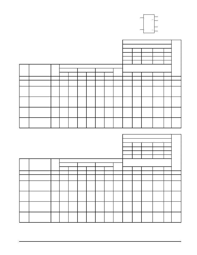
ELECTRICAL CHARACTERISTICS
The MC12040 has been designed to meet the dc
specifications shown in the test table after thermal
equilibrium has been established. Outputs are terminated
through a 50 ohm resistor to +3.0 V for +5.0 V tests and
through a 50 ohm resistor to –2.0 V for –5.2 V tests.
6
R
9
V
U
U
4
3
D
12
D
11
TEST VOLTAGE VALUES
(Volts)
@ Test Temperature
VIHmax
VILmin
VIHAmin
VILAmax
VEE
0
°
C
–0.840
–1.870
–1.145
–1.490
–5.2
25
°
C
–0.810
–1.850
–1.105
–1.475
–5.2
Supply Voltage = –5.2V
75
°
C
–0.720
–1.830
–1.045
–1.450
–5.2
Pin
Under
Test
MC12040
TEST VOLTAGE APPLIED TO PINS BELOW
0
°
C
25
°
C
75
°
C
(Gnd
Symbol
Characteristics
Min
Max
Min
Max
Min
Max
Unit
VIHmax
VILmin
VIHAmin
VILAmax
VEE
7
(VCC)
IE
Power Supply Drain
7
–120
–60
mAdc
1,14
IINH
Input Current
6
9
350
350
μ
Adc
6
9
7
7
1,14
1,14
VOH
1
Logic “1”
Output Voltage
3
4
11
12
–1.000
–0.840
–0.960
–0.810
–0.900
–0.720
Vdc
7
1,14
VOL
1
Logic “0”
Output Voltage
3
4
11
12
–1.870
–1.635
–1.850
–1.620
–1.830
–1.595
Vdc
7
1,14
VOHA
2
Logic “1”
Input Voltage
3
4
11
12
–1.020
–0.980
–0.920
Vdc
6.9
7
1,14
VOLA
2
Logic “0”
Input Voltage
3
4
11
12
–1.615
–1.600
–1.575
Vdc
9
6
9
6
6
9
6
9
7
1,14
TEST VOLTAGE VALUES
(Volts)
@ Test Temperature
VIHmax
VILmin
VIHAmin
VILAmax
VEE
0
°
C
+4.160
+3.130
+3.855
+3.510
+5.0
25
°
C
+4.190
+3.150
+3.895
+3.525
+5.0
Supply Voltage = +5.0V
75
°
C
+4.280
+3.170
+3.955
+3.550
+5.0
Pi
Under
Test
MC12040
TEST VOLTAGE APPLIED TO PINS BELOW
0
°
C
25
°
C
75
°
C
(Gnd
Symbol
Characteristics
Min
Max
Min
Max
Min
Max
Unit
VIHmax
VILmin
VIHAmin
VILAmax
VEE
1,14
(VCC)
IE
Power Supply Drain
7
–115
–60
mAdc
7
IINH
Input Current
6
9
350
350
μ
Adc
6
9
1,14
1,14
7
7
VOH
1
Logic “1”
Output Voltage
3
4
11
12
4.000
4.160
4.040
4.190
4.100
4.280
Vdc
1,14
7
VOL
1
Logic “0”
Output Voltage
3
4
11
12
3.190
3.430
3.210
3.440
3.230
3.470
Vdc
1,14
7
VOHA
2
Logic “1”
Input Voltage
3
4
11
12
3.980
4.020
4.080
Vdc
6.9
1,14
7
VOLA
2
Logic “0”
Input Voltage
3
4
11
12
3.450
3.460
3.490
Vdc
9
6
9
6
6
9
6
9
1,14
7
NOTE:
For more information on using an ECL device in a
+5V system, refer to Motorola Application Note
AN1406/D, “Designing with PECL (ECL at +5.0V)”
相關PDF資料 |
PDF描述 |
|---|---|
| MC12040P | PHASE-FREQUENCY DETECTOR |
| MC12052AD | MECL PLL COMPONENTS ±64/65, ±128/129 LOW POWER DUAL MODULUS PRESCALER |
| MC12052 | 30 AMP MINIATURE POWER RELAY |
| MC12052A | 30 AMP MINIATURE POWER RELAY |
| MC12052ASD | MECL PLL COMPONENTS ±64/65, ±128/129 LOW POWER DUAL MODULUS PRESCALER |
相關代理商/技術參數 |
參數描述 |
|---|---|
| MC12040P | 制造商:Motorola Inc 功能描述: |
| MC1204L | 制造商:Rochester Electronics LLC 功能描述:- Bulk |
| MC1205 | 制造商:Rochester Electronics LLC 功能描述:- Bulk |
| MC12052 | 制造商:MOTOROLA 制造商全稱:Motorola, Inc 功能描述:MECL PLL COMPONENTS ±64/65, ±128/129 LOW POWER DUAL MODULUS PRESCALER |
| MC12052A | 制造商:MOTOROLA 制造商全稱:Motorola, Inc 功能描述:MECL PLL COMPONENTS ±64/65, ±128/129 LOW POWER DUAL MODULUS PRESCALER |
發(fā)布緊急采購,3分鐘左右您將得到回復。