- 您現(xiàn)在的位置:買賣IC網(wǎng) > PDF目錄384715 > MAX9750CEUI (MAXIM INTEGRATED PRODUCTS INC) 2.6W Stereo Audio Power Amplifiers and DirectDrive Headphone Amplifiers PDF資料下載
參數(shù)資料
| 型號: | MAX9750CEUI |
| 廠商: | MAXIM INTEGRATED PRODUCTS INC |
| 元件分類: | 音頻控制 |
| 英文描述: | 2.6W Stereo Audio Power Amplifiers and DirectDrive Headphone Amplifiers |
| 中文描述: | VOLUME CONTROL CIRCUIT, PDSO28 |
| 封裝: | 4.40 MM, MO-153AE, TSSOP-28 |
| 文件頁數(shù): | 12/31頁 |
| 文件大?。?/td> | 673K |
| 代理商: | MAX9750CEUI |
第1頁第2頁第3頁第4頁第5頁第6頁第7頁第8頁第9頁第10頁第11頁當(dāng)前第12頁第13頁第14頁第15頁第16頁第17頁第18頁第19頁第20頁第21頁第22頁第23頁第24頁第25頁第26頁第27頁第28頁第29頁第30頁第31頁
M
2.6W Stereo Audio Power Amplifiers and
DirectDrive Headphone Amplifiers
12
______________________________________________________________________________________
significant amount of DC current flows to the headphone,
resulting in unnecessary power dissipation and possible
damage to both headphone and headphone amplifier.
Maxim’s patented DirectDrive architecture uses a charge
pump to create an internal negative supply voltage. This
allows the MAX9750/MAX9751/MAX9755 headphone
amplifier output to be biased about GND, almost dou-
bling the dynamic range while operating from a single
supply. With no DC component, there is no need for the
large DC-blocking capacitors. Instead of two large
capacitors (220μF typ), the MAX9750/MAX9751/
MAX9755 charge pump requires only two small ceramic
capacitors (1μF typ), conserving board space, reducing
cost, and improving the frequency response of the head-
phone amplifier. See the Output Power vs. Charge-Pump
Capacitance and Load Resistance graph in the
Typical
Operating Characteristics
for details of the possible
capacitor values.
Previous attempts to eliminate the output coupling
capacitors involved biasing the headphone return
(sleeve) to the DC bias voltage of the headphone
amplifiers. This method raised some issues:
1) The sleeve is typically grounded to the chassis. Using
this biasing approach, the sleeve must be isolated
from system ground, complicating product design.
2) During an ESD strike, the amplifier’s ESD structures
are the only path to system ground. The amplifier
must be able to withstand the full ESD strike.
3) When using the headphone jack as a lineout to other
equipment, the bias voltage on the sleeve may con-
flict with the ground potential from other equipment,
resulting in large ground-loop current and possible
damage to the amplifiers.
Low-Frequency Response
In addition to the cost and size disadvantages, the DC-
blocking capacitors limit the low-frequency response of
the amplifier and distort the audio signal:
1) The impedance of the headphone load to the DC-
blocking capacitor forms a highpass filter with the
-3dB point determined by:
where R
L
is the impedance of the headphone and
C
OUT
is the value of the DC-blocking capacitor.
The highpass filter is required by conventional sin-
gle-ended, single-supply headphone amplifiers to
block the midrail DC component of the audio signal
from the headphones. Depending on the -3dB point,
the filter can attenuate low-frequency signals within
the audio band. Larger values of C
OUT
reduce the
attenuation but are physically larger, more expen-
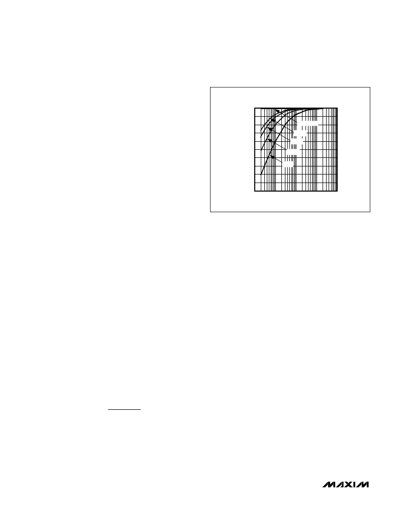
sive capacitors. Figure 3 shows the relationship
between the size of C
OUT
and the resulting low-fre-
quency attenuation. Note that the -3dB point for a
16
headphone with a 100μF blocking capacitor is
100Hz, well within the audio band.
2) The voltage coefficient of the capacitor, the change
in capacitance due to a change in the voltage
across the capacitor, distorts the audio signal. At
frequencies around the -3dB point, the reactance of
the capacitor dominates, and the voltage coefficient
appears as frequency-dependent distortion. Figure
4 shows the THD+N introduced by two different
capacitor dielectrics. Note that around the -3dB
point, THD+N increases dramatically.
The combination of low-frequency attenuation and fre-
quency-dependent distortion compromises audio
reproduction. DirectDrive improves low-frequency
reproduction in portable audio equipment that empha-
sizes low-frequency effects such as multimedia lap-
tops, and MP3, CD, and DVD players.
Charge Pump
The MAX9750/MAX9751/MAX9755 feature a low-noise
charge pump. The 550kHz switching frequency is well
beyond the audio range, and does not interfere with the
audio signals. The switch drivers feature a controlled
switching speed that minimizes noise generated by turn-
on and turn-off transients. Limiting the switching speed of
the charge pump minimizes the di/dt noise caused by the
f
R C
2
π
dB
3
=
1
0
-30
10
100
1k
10k
100k
LOW-FREQUENCY ROLLOFF
(R
L
= 16
)
-24
-27
-12
-15
-18
-21
-6
-9
-3
FREQUENCY (Hz)
A
DirectDrive
330
μ
F
220
μ
F
100
μ
F
33
μ
F
Figure 3. Low-Frequency Attenuation of Common DC-Blocking
Capacitor Values
相關(guān)PDF資料 |
PDF描述 |
|---|---|
| MAX9750AETI | 2.6W Stereo Audio Power Amplifiers and DirectDrive Headphone Amplifiers |
| MAX9750AEUI | 2.6W Stereo Audio Power Amplifiers and DirectDrive Headphone Amplifiers |
| MAX9750BETI | 2.6W Stereo Audio Power Amplifiers and DirectDrive Headphone Amplifiers |
| MAX9759 | 3.2W, High-Efficiency, Low-EMI, Filterless, Class D Audio Amplifier |
| MAX975ESA | Octal Transparent D-type Latches With 3-State Outputs 20-LCCC -55 to 125 |
相關(guān)代理商/技術(shù)參數(shù) |
參數(shù)描述 |
|---|---|
| MAX9751ETI+ | 功能描述:音頻放大器 Integrated Circuits (ICs) RoHS:否 制造商:STMicroelectronics 產(chǎn)品:General Purpose Audio Amplifiers 輸出類型:Digital 輸出功率: THD + 噪聲: 工作電源電壓:3.3 V 電源電流: 最大功率耗散: 最大工作溫度: 安裝風(fēng)格:SMD/SMT 封裝 / 箱體:TQFP-64 封裝:Reel |
| MAX9751ETI+T | 功能描述:音頻放大器 Integrated Circuits (ICs) RoHS:否 制造商:STMicroelectronics 產(chǎn)品:General Purpose Audio Amplifiers 輸出類型:Digital 輸出功率: THD + 噪聲: 工作電源電壓:3.3 V 電源電流: 最大功率耗散: 最大工作溫度: 安裝風(fēng)格:SMD/SMT 封裝 / 箱體:TQFP-64 封裝:Reel |
| MAX9751EUI | 制造商:Rochester Electronics LLC 功能描述: 制造商:Maxim Integrated Products 功能描述: |
| MAX9752AETI+ | 功能描述:音頻放大器 Integrated Circuits (ICs) RoHS:否 制造商:STMicroelectronics 產(chǎn)品:General Purpose Audio Amplifiers 輸出類型:Digital 輸出功率: THD + 噪聲: 工作電源電壓:3.3 V 電源電流: 最大功率耗散: 最大工作溫度: 安裝風(fēng)格:SMD/SMT 封裝 / 箱體:TQFP-64 封裝:Reel |
| MAX9752AETI+T | 功能描述:音頻放大器 Integrated Circuits (ICs) RoHS:否 制造商:STMicroelectronics 產(chǎn)品:General Purpose Audio Amplifiers 輸出類型:Digital 輸出功率: THD + 噪聲: 工作電源電壓:3.3 V 電源電流: 最大功率耗散: 最大工作溫度: 安裝風(fēng)格:SMD/SMT 封裝 / 箱體:TQFP-64 封裝:Reel |
發(fā)布緊急采購,3分鐘左右您將得到回復(fù)。