- 您現在的位置:買賣IC網 > PDF目錄11688 > MAX9272GTM+T (Maxim Integrated Products)IC DSERIALIZER 28BIT GMSL 48TQFN PDF資料下載
參數資料
| 型號: | MAX9272GTM+T |
| 廠商: | Maxim Integrated Products |
| 文件頁數: | 33/47頁 |
| 文件大?。?/td> | 0K |
| 描述: | IC DSERIALIZER 28BIT GMSL 48TQFN |
| 標準包裝: | 2,500 |
| 系列: | * |
第1頁第2頁第3頁第4頁第5頁第6頁第7頁第8頁第9頁第10頁第11頁第12頁第13頁第14頁第15頁第16頁第17頁第18頁第19頁第20頁第21頁第22頁第23頁第24頁第25頁第26頁第27頁第28頁第29頁第30頁第31頁第32頁當前第33頁第34頁第35頁第36頁第37頁第38頁第39頁第40頁第41頁第42頁第43頁第44頁第45頁第46頁第47頁
MAX9272
28-Bit GMSL Deserializer for Coax or STP Cable
39
Maxim Integrated
(RTR), the CML/coax driver termination resistor (RTD), and
the series AC-coupling capacitors (C). The RC time con-
stant, for four equal-value series capacitors, is (C x (RTD
+ RTR))/4. RTD and RTR are required to match the trans-
mission line impedance (usually 100I differential and
50I single-ended). This leaves the capacitor selection
to change the system time constant. Use 0.2FF or larger
high-frequency surface-mount ceramic capacitors, with
sufficient voltage rating to withstand a short to battery, to
pass the lower speed reverse control-channel signal. Use
capacitors with a case size less than 3.2mm x 1.6mm to
have lower parasitic effects to the high-speed signal.
Power-Supply Circuits and Bypassing
The deserializer uses an AVDD and DVDD of 1.7V to
1.9V. All inputs and outputs, except for the serial input,
derive power from an IOVDD of 1.7V to 3.6V that scales
with IOVDD. Proper voltage-supply bypassing is essen-
tial for high-frequency circuit stability. The GPI-to-GPO
delay is 0.35ms (max). Keep the time between GPI trans-
missions to a minimum 0.35ms.
Power-Supply Table
Power-supply currents shown in the Electrical
Characteristics table are the sum of the currents from
AVDD, DVDD, and IOVDD. Typical currents from the
individual power supplies are shown in Table 14.
Cables and Connectors
Interconnect for CML typically has a differential imped-
ance of 100I. Use cables and connectors that have
matched differential impedance to minimize impedance
discontinuities. Coax cables typically have a characteris-
tic impedance of 50I (contact the factory for 75I opera-
tion). Table 15 lists the suggested cables and connectors
used in the GMSL link.
Board Layout
Separate the LVCMOS logic signals and CML/coax high-
speed signals to prevent crosstalk. Use a four-layer PCB
with separate layers for power, ground, CML/coax, and
LVCMOS logic signals. Layout PCB traces close to each
other for a 100I differential characteristic impedance.
The trace dimensions depend on the type of trace used
(microstrip or stripline). Note that two 50I PCB traces
do not have 100I differential impedance when brought
close together—the impedance goes down when the
traces are brought closer. Use a 50I trace for the single-
ended output when driving coax.
Route the PCB traces for differential CML channel in par-
allel to maintain the differential characteristic impedance.
Avoid vias. Keep PCB traces that make up a differential
pair equal length to avoid skew within the differential pair.
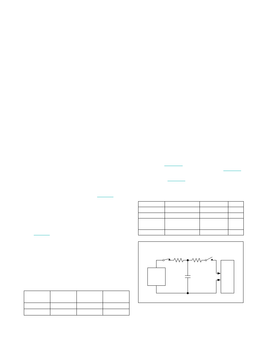
ESD Protection
ESD tolerance is rated for Human Body Model, IEC
61000-4-2, and ISO 10605. The ISO 10605 and IEC
61000-4-2 standards specify ESD tolerance for electronic
systems. The serial link inputs are rated for ISO 10605
ESD protection and IEC 61000-4-2 ESD protection. All
pins are tested for the Human Body Model. The Human
Body Model discharge components are CS = 100pF and
The ISO 10605 discharge components are CS = 330pF
Table 14. Typical Power-Supply Currents
(Using Worst-Case Input Pattern)
Table 15. Suggested Connectors and
Cables for GMSL
Figure 32. Human Body Model ESD Test Circuit
SUPPLIER
CONNECTOR
CABLE
TYPE
Rosenberger
59S2AX-400A5-Y
RG174
Coax
JAE
MX38-FF
A-BW-Lxxxxx
STP
Nissei
GT11L-2S
F-2WME
AWG28
STP
Rosenberger
D4S10A-40ML5-Z
Dacar 538
STP
PCLK
(MHz)
AVDD
(mA)
DVDD
(mA)
IOVDD
(mA)
25
25.1
9.2
10.3
50
33.3
13.7
13.3
STORAGE
CAPACITOR
HIGH-
VOLTAGE
DC
SOURCE
DEVICE
UNDER
TEST
CHARGE-CURRENT-
LIMIT RESISTOR
DISCHARGE
RESISTANCE
1MI
RD
1.5kI
CS
100pF
相關PDF資料 |
PDF描述 |
|---|---|
| MAX9273GTL/V+T | IC SERIALIZER 22BIT GMSL 40TQFN |
| MAX9273GTL+T | IC SERIALIZER 22BIT GMSL 40TQFN |
| MAX9271GTJ/V+T | IC SERIALIZER 16BIT GMSL 32TQFN |
| VI-B3V-CU-S | CONVERTER MOD DC/DC 5.8V 200W |
| MAX9271GTJ+T | IC SERIALIZER 16BIT GMSL 32TQFN |
相關代理商/技術參數 |
參數描述 |
|---|---|
| MAX9272GTV+ | 制造商:MAXIM 制造商全稱:Maxim Integrated Products 功能描述:28-Bit GMSL Deserializer for Coax or STP Cable |
| MAX9273 | 制造商:MAXIM 制造商全稱:Maxim Integrated Products 功能描述:22-Bit GMSL Serializer with Coax or STP Cable Drive |
| MAX9273GTL/V+ | 功能描述:串行器/解串器 - Serdes 1.5Gbps 22-bit Coax/STP serializer RoHS:否 制造商:Texas Instruments 類型:Deserializer 數據速率:1.485 Gbit/s 輸入類型:ECL/LVDS 輸出類型:LVCMOS 輸入端數量:1 輸出端數量:20 工作電源電壓:2.375 V to 2.625 V 工作溫度范圍:0 C to + 70 C 封裝 / 箱體:TQFP-64 |
| MAX9273GTL/V+T | 功能描述:串行器/解串器 - Serdes 1.5Gbps 22-bit Coax/STP serializer RoHS:否 制造商:Texas Instruments 類型:Deserializer 數據速率:1.485 Gbit/s 輸入類型:ECL/LVDS 輸出類型:LVCMOS 輸入端數量:1 輸出端數量:20 工作電源電壓:2.375 V to 2.625 V 工作溫度范圍:0 C to + 70 C 封裝 / 箱體:TQFP-64 |
| MAX9273GTL+ | 功能描述:串行器/解串器 - Serdes 1.5Gbps 22-bit Coax/STP serializer RoHS:否 制造商:Texas Instruments 類型:Deserializer 數據速率:1.485 Gbit/s 輸入類型:ECL/LVDS 輸出類型:LVCMOS 輸入端數量:1 輸出端數量:20 工作電源電壓:2.375 V to 2.625 V 工作溫度范圍:0 C to + 70 C 封裝 / 箱體:TQFP-64 |
發(fā)布緊急采購,3分鐘左右您將得到回復。