- 您現(xiàn)在的位置:買賣IC網(wǎng) > PDF目錄383509 > MAX818LESA (MAXIM INTEGRATED PRODUCTS INC) Dual 4-Input Positive-AND Gates 14-CDIP -55 to 125 PDF資料下載
參數(shù)資料
| 型號: | MAX818LESA |
| 廠商: | MAXIM INTEGRATED PRODUCTS INC |
| 元件分類: | 電源管理 |
| 英文描述: | Dual 4-Input Positive-AND Gates 14-CDIP -55 to 125 |
| 中文描述: | 1-CHANNEL POWER SUPPLY SUPPORT CKT, PDSO8 |
| 封裝: | 0.150 INCH, SOIC-8 |
| 文件頁數(shù): | 15/16頁 |
| 文件大小: | 114K |
| 代理商: | MAX818LESA |
M
+5V Mic roproc essor S upervisory Circ uits
______________________________________________________________________________________
15
____Pin Configurations (c ontinued)
__________Typic al Operating Circ uit
WDI
GND
CE OUT
CE IN
1
2
8
7
BATT
RESET
V
CC
OUT
MAX818
DIP/SO/
μ
MAX
TOP VIEW
3
4
6
5
MR
GND
PFO
PFI
1
2
8
7
BATT
RESET
V
CC
OUT
MAX819
DIP/SO/
μ
MAX
3
4
6
5
CE IN*
*CE IN AND CE OUT APPLY TOMAX818 ONLY.
**WDI APPLIES TOMAX817/MAX818 ONLY.
BATT
RESET
I/O
OUT
CMOS
RAM
RESET
WDI**
CE OUT*
GND
0.1
μ
F
0.1
μ
F
0.1
μ
F
MAX817
MAX818
MAX819
V
CC
ADDRESS
DECODE
REAL-
TIME
CLOCK
A0–A15
μ
P
+5V
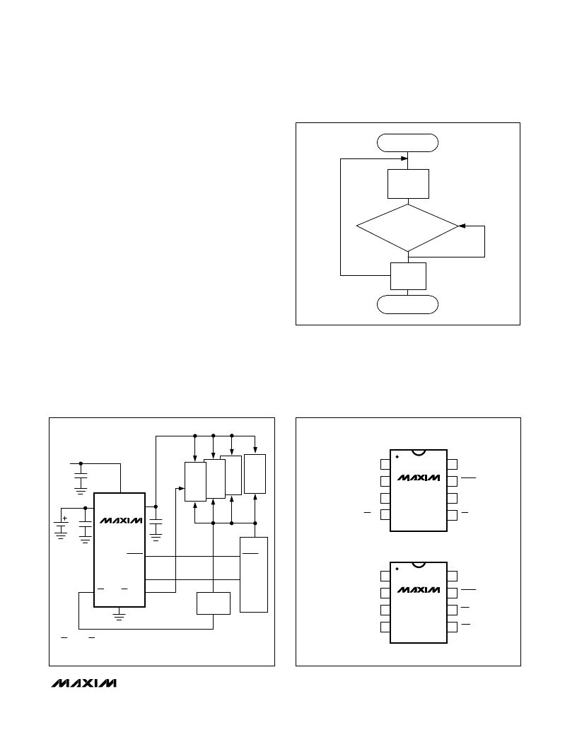
Watc hdog S oftware Considerations
(MAX 817/MAX 818)
To help the watchdog timer monitor software execution
more closely, set and reset the watchdog input at different
points in the program, rather than “pulsing” the watchdog
input high-low-high or low-high-low. This technique avoids
a “stuck” loop, in which the watchdog timer would contin-
ue to be reset within the loop, keeping the watchdog from
timing out. Figure 15 shows an example of a flow diagram
where the I/O driving the watchdog input is set high at the
beginning of the program, set low at the beginning of
every subroutine or loop, then set high again when the
program returns to the beginning. If the program should
“hang” in any subroutine, the problem would quickly be
corrected, since the I/O is continually set low and the
watchdog timer is allowed to time out, triggering a reset or
an interrupt. As described in the Watchdog Input Current
section, this scheme results in higher average WDI input
current than does the method of leaving WDI low for the
majority of the timeout period and periodically pulsing it
low-high-low.
Figure 15. Watchdog Flow Diagram
START
SET
WDI
LOW
SUBROUTINE
OR PROGRAM LOOP,
SET WDI
HIGH
RETURN
END
相關(guān)PDF資料 |
PDF描述 |
|---|---|
| MAX818M | Dual 4-Input Positive-AND Gates 20-LCCC -55 to 125 |
| MAX818MCSA | Dual 4-Input Positive-AND Gates 14-CDIP -55 to 125 |
| MAX818MCUA | +5V Microprocessor Supervisory Circuits |
| MAX818MCPA | FPGA - 200000 SYSTEM GATE 2.5 VOLT - NOT RECOMMENDED for NEW DESIGN |
| MAX817LESA | +5V Microprocessor Supervisory Circuits |
相關(guān)代理商/技術(shù)參數(shù) |
參數(shù)描述 |
|---|---|
| MAX818LESA+ | 功能描述:監(jiān)控電路 5V MPU Supervisor RoHS:否 制造商:STMicroelectronics 監(jiān)測電壓數(shù): 監(jiān)測電壓: 欠電壓閾值: 過電壓閾值: 輸出類型:Active Low, Open Drain 人工復位:Resettable 監(jiān)視器:No Watchdog 電池備用開關(guān):No Backup 上電復位延遲(典型值):10 s 電源電壓-最大:5.5 V 最大工作溫度:+ 85 C 安裝風格:SMD/SMT 封裝 / 箱體:UDFN-6 封裝:Reel |
| MAX818LESA+T | 功能描述:監(jiān)控電路 5V MPU Supervisor RoHS:否 制造商:STMicroelectronics 監(jiān)測電壓數(shù): 監(jiān)測電壓: 欠電壓閾值: 過電壓閾值: 輸出類型:Active Low, Open Drain 人工復位:Resettable 監(jiān)視器:No Watchdog 電池備用開關(guān):No Backup 上電復位延遲(典型值):10 s 電源電壓-最大:5.5 V 最大工作溫度:+ 85 C 安裝風格:SMD/SMT 封裝 / 箱體:UDFN-6 封裝:Reel |
| MAX818LESA-T | 功能描述:監(jiān)控電路 RoHS:否 制造商:STMicroelectronics 監(jiān)測電壓數(shù): 監(jiān)測電壓: 欠電壓閾值: 過電壓閾值: 輸出類型:Active Low, Open Drain 人工復位:Resettable 監(jiān)視器:No Watchdog 電池備用開關(guān):No Backup 上電復位延遲(典型值):10 s 電源電壓-最大:5.5 V 最大工作溫度:+ 85 C 安裝風格:SMD/SMT 封裝 / 箱體:UDFN-6 封裝:Reel |
| MAX818M | 制造商:MAXIM 制造商全稱:Maxim Integrated Products 功能描述:+5V Microprocessor Supervisory Circuits |
| MAX818MCPA | 功能描述:監(jiān)控電路 RoHS:否 制造商:STMicroelectronics 監(jiān)測電壓數(shù): 監(jiān)測電壓: 欠電壓閾值: 過電壓閾值: 輸出類型:Active Low, Open Drain 人工復位:Resettable 監(jiān)視器:No Watchdog 電池備用開關(guān):No Backup 上電復位延遲(典型值):10 s 電源電壓-最大:5.5 V 最大工作溫度:+ 85 C 安裝風格:SMD/SMT 封裝 / 箱體:UDFN-6 封裝:Reel |
發(fā)布緊急采購,3分鐘左右您將得到回復。