- 您現(xiàn)在的位置:買(mǎi)賣(mài)IC網(wǎng) > PDF目錄383509 > MAX817 (Maxim Integrated Products, Inc.) Dual 4-Input Positive-NAND Gates 20-LCCC -55 to 125 PDF資料下載
參數(shù)資料
| 型號(hào): | MAX817 |
| 廠商: | Maxim Integrated Products, Inc. |
| 英文描述: | Dual 4-Input Positive-NAND Gates 20-LCCC -55 to 125 |
| 中文描述: | +5V微處理器監(jiān)控電路 |
| 文件頁(yè)數(shù): | 7/16頁(yè) |
| 文件大小: | 114K |
| 代理商: | MAX817 |
第1頁(yè)第2頁(yè)第3頁(yè)第4頁(yè)第5頁(yè)第6頁(yè)當(dāng)前第7頁(yè)第8頁(yè)第9頁(yè)第10頁(yè)第11頁(yè)第12頁(yè)第13頁(yè)第14頁(yè)第15頁(yè)第16頁(yè)
M
+5V Mic roproc essor S upervisory Circ uits
_______________________________________________________________________________________
7
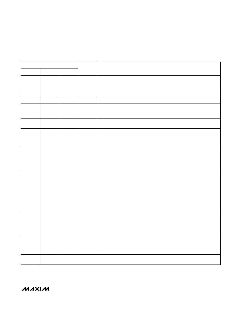
______________________________________________________________Pin Desc ription
Ground. 0V reference for all signals.
3
3
Input Supply Voltage, +5V input.
2
2
Supply Output for CMOS RAM. When V
CC
rises above the reset threshold
or above V
BATT
, OUT is connected to V
CC
through an internal P-channel
MOSFET switch. When V
CC
falls below V
BATT
, BATT connects to OUT.
1
1
GND
3
V
CC
2
OUT
1
Power-Fail Comparator Output. When PFI is less than V
PFT
or when V
CC
is
below V
BATT
,
PFO
goes low; otherwise
PFO
remains high.
PFO
is also used to
enable the battery freshness seal (see Battery Freshness Seal and Power-Fail
Comparatorsections).
—
5
Chip-Enable Input. The input to the chip-enable gating circuit. Connect to
ground if unused.
4
—
Power-Fail Comparator Input. When V
PFI
is below V
PFT
or when V
CC
is below
V
BATT
,
PFO
goes low; otherwise,
PFO
remains high (see Power-Fail Comparator
section). Connect to ground if unused.
—
4
PFO
5
CE
IN
—
PFI
4
Backup-Battery Input. When V
CC
falls below V
BATT
, OUT switches from V
CC
to
BATT. When V
CC
rises above V
BATT
, OUT reconnects to V
CC
.
8
8
Active-Low Reset Output. Pulses low for 200ms when triggered and remains
low whenever V
CC
is below the reset threshold or when
MR
is a logic low. It
remains low for 200ms after V
CC
rises above the reset threshold, the watchdog
triggers a reset, or
MR
goes low to high.
7
7
BATT
8
RESET
7
Manual Reset Input. A logic low on
MR
asserts reset. Reset remains asserted
for as long as
MR
is held low and for 200ms after
MR
returns high. The active-
low input has an internal 63k
pull-up resistor. It can be driven from a TTL- or
CMOS-logic line or shorted to ground with a switch. Leave open, or connect to
V
CC
if unused.
—
—
Watchdog Input. If WDI remains either high or low for longer than the watch-
dog timeout period, the internal watchdog timer runs out and a reset is trig-
gered. If WDI is left unconnected or is connected to a high-impedance
three-state buffer, the watchdog feature is disabled. The internal watchdog
timer clears whenever reset is asserted, WDI is three-stated, or WDI sees a ris-
ing or falling edge. The WDI input is designed to be driven by a three-stated-
output device with a maximum high-impedance leakage current of 10μA and a
maximum output capacitance of 200pF. The output device must also be capa-
ble of sinking and sourcing 200μA when active.
6
6
Chip-Enable Output.
CE
OUT goes low only if
CE
IN is low while reset is not
asserted. If
CE
IN is low when reset is asserted,
CE
OUT will remain low for
15μs or until
CE
IN goes high, whichever occurs first.
CE
OUT is pulled up to
OUT in battery-backup mode.
CE
OUT is also used to enable the battery
freshness seal (see Battery Freshness Seal section).
5
—
MR
6
WDI
—
CE
OUT
—
FUNCTION
NAME
MAX817
MAX818
MAX819
PIN
相關(guān)PDF資料 |
PDF描述 |
|---|---|
| MAX817L | Dual 4-Input Positive-NAND Gates 14-CDIP -55 to 125 |
| MAX817M | Dual 4-Input Positive-NAND Gates 14-CFP -55 to 125 |
| MAX817MESA | Dual 4-Input Positive-NAND Gates 14-CDIP |
| MAX818L | Dual 4-Input Positive-NAND Gates 14-CFP |
| MAX818LCPA | +5V Microprocessor Supervisory Circuits |
相關(guān)代理商/技術(shù)參數(shù) |
參數(shù)描述 |
|---|---|
| MAX817_CPA | 制造商:MAXIM 制造商全稱(chēng):Maxim Integrated Products 功能描述:+5V Microprocessor Supervisory Circuits |
| MAX817_CSA | 制造商:MAXIM 制造商全稱(chēng):Maxim Integrated Products 功能描述:+5V Microprocessor Supervisory Circuits |
| MAX817_CUA | 制造商:MAXIM 制造商全稱(chēng):Maxim Integrated Products 功能描述:+5V Microprocessor Supervisory Circuits |
| MAX817_EPA | 制造商:MAXIM 制造商全稱(chēng):Maxim Integrated Products 功能描述:+5V Microprocessor Supervisory Circuits |
| MAX817_ESA | 制造商:MAXIM 制造商全稱(chēng):Maxim Integrated Products 功能描述:+5V Microprocessor Supervisory Circuits |
發(fā)布緊急采購(gòu),3分鐘左右您將得到回復(fù)。