- 您現(xiàn)在的位置:買賣IC網(wǎng) > PDF目錄384702 > MAX79E (Maxim Integrated Products, Inc.) 3.0V/3.3V Adjustable Microprocessor Supervisory Circuits PDF資料下載
參數(shù)資料
| 型號: | MAX79E |
| 廠商: | Maxim Integrated Products, Inc. |
| 英文描述: | 3.0V/3.3V Adjustable Microprocessor Supervisory Circuits |
| 中文描述: | 3.0V/3.3V可調微處理器監(jiān)控電路 |
| 文件頁數(shù): | 2/20頁 |
| 文件大小: | 150K |
| 代理商: | MAX79E |
μA
M
3.0V /3.3V Adjustable Mic roproc essor
S upervisory Circ uits
2
_______________________________________________________________________________________
ABSOLUTE MAXIMUM RATINGS
Terminal Voltage (with respect to GND)
V
CC
........................................................................-0.3V to 6.0V
V
BATT
.....................................................................-0.3V to 6.0V
All Other Inputs ..................-0.3V to the higher of V
CC
or V
BATT
Continuous Input Current
V
CC
.................................................................................200mA
V
BATT
................................................................................50mA
GND ..................................................................................20mA
Output Current
V
OUT
................................................................................200mA
All Other Outputs ..............................................................20mA
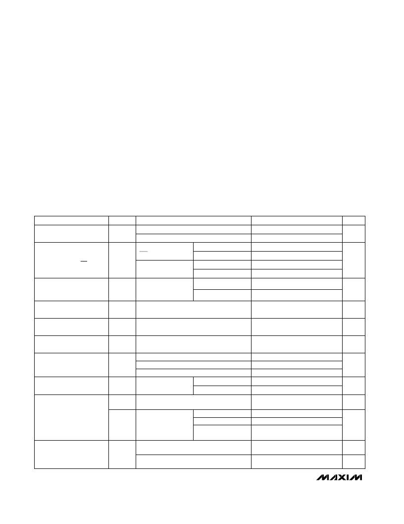
ELECTRICAL CHARACTERISTICS
(V
CC
= 3.17V to 5.5V for the MAX793T/MAX795T, V
CC
= 3.02V to 5.5V for the MAX793S/MAX795S, V
CC
= 2.72V to 5.5V for the
MAX793R/MAX794/MAX795R, V
BATT
= 3.6V, T
A
= T
MIN
to T
MAX
, unless otherwise noted. Typical values are at T
A
= +25°C.)
Stresses beyond those listed under “Absolute Maximum Ratings” may cause permanent damage to the device. These are stress ratings only, and functional
operation of the device at these or any other conditions beyond those indicated in the operational sections of the specifications is not implied. Exposure to
absolute maximum rating conditions for extended periods may affect device reliability.
Continuous Power Dissipation (T
A
= +70°C)
8-Pin Plastic DIP (derate 9.09mW/°C above +70°C) .....727mW
8-Pin SO (derate 5.88mW/°C above +70°C)..................471mW
16-Pin Plastic DIP (derate 10.53mW/°C above +70°C) .842mW
16-Pin Narrow SO (derate 9.52mW/°C above +70°C)...696mW
Operating Temperature Ranges
MAX793_C_ _/MAX794C_ _/MAX795_C_ _ ......... 0°C to +70°C
MAX793_E_ _/MAX794E_ _/MAX795_E_ _ ........-40°C to +85°C
Storage Temperature Range.............................-65°C to +160°C
Lead Temperature (soldering, 10sec) .............................+300°C
MAX79_E
MAX79_C
V
BATT
> V
CC
(Note 6)
I
OUT
= 250μA (Note 4)
I
OUT
= 30mA (Note 4)
V
SW
> V
CC
> 1.75V (Note 5)
I
OUT
= 75mA
V
BATT
= 2.3V
CONDITIONS
Battery Switch Threshold
(V
CC
falling)
V
2.30
2.41
2.52
V
SW
2.55
2.68
2.80
2.69
2.82
2.95
mV
20
65
V
CC
-
V
BATT
V
V
BATT
- 0.14
V
OUT
OUT Output Voltage in
Battery-Backup Mode
V
BATT
- 0.1
V
BATT
- 0.034
V
1.1
5.5
60
1.0
5.5
Operating Voltage Range,
V
CC
, V
BATT
(Note 1)
V
V
CC
- 0.001
V
CC
- 0.5mV
V
OUT
OUT Output Voltage in
Normal Mode
V
CC
- 0.12
V
CC
- 0.050
V
CC
- 0.3
V
CC
- 0.125
μA
0.5
Battery Leakage Current
(Note 3)
μA
1
BATT Supply Current
(excluding I
OUT
) (Note 2)
UNITS
MIN
TYP
MAX
SYMBOL
PARAMETER
V
CC
= 0V, V
OUT
= 0V
μA
1
BATT Leakage Current,
Freshness Seal Enabled
I
OUT
= 250μA
I
OUT
= 1mA
MAX793T/MAX795T
MAX793S/MAX795S
MAX793R/MAX795R/
MAX794
This value is identical to the reset threshold,
V
CC
rising for V
BATT
> V
RST
V
CC
-
V
BATT
V
BATT
< V
RST
mV
25
65
Battery Switch Threshold
(V
CC
rising) (Note 7)
MAX793/MAX794,
MR = V
CC
μA
62
35
80
50
I
SUPPLY
46
V
CC
Supply Current
(excluding I
OUT
, I
CE OUT
)
V
CC
= 2.1V,
V
BATT
= 2.3V
μA
32
45
I
SUPPLY
V
CC
Supply Current in
Battery-Backup Mode
(excluding I
OUT
)
V
CC
< 3.6V
V
CC
< 5.5V
V
CC
< 3.6V
V
CC
< 5.5V
MAX793/MAX794
MAX795
24
35
MAX795
49
70
相關PDF資料 |
PDF描述 |
|---|---|
| MAX794ESE | 3.0V/3.3V Adjustable Microprocessor Supervisory Circuits |
| MAX794CPE | Quadruple 2-Input Exclusive-OR Gates 14-CDIP -55 to 125 |
| MAX794CSE | Quadruple 2-Input Exclusive-OR Gates 14-CFP -55 to 125 |
| MAX794EPE | 3.0V/3.3V Adjustable Microprocessor Supervisory Circuits |
| MAX793CPE | 3.0V/3.3V Adjustable Microprocessor Supervisory Circuits |
相關代理商/技術參數(shù) |
參數(shù)描述 |
|---|---|
| MAX8 | 制造商:Lanzar 功能描述:4Ohm 600W Peak 8 Paper Cone Woofer 制造商:LANZAR 功能描述:8 PAPER CONE WOOFER 4OHM 600W PEAK |
| MAX-80 | 功能描述:保險絲 32V 80A Blade Clear RoHS:否 制造商:Littelfuse 產品:Surface Mount Fuses 電流額定值:0.5 A 電壓額定值:600 V 保險絲類型:Fast Acting 保險絲大小/組:Nano 尺寸:12.1 mm L x 4.5 mm W 安裝風格: 端接類型:SMD/SMT 系列:485 |
| MAX800 | 制造商:MAXIM 制造商全稱:Maxim Integrated Products 功能描述:Microprocessor Supervisory Circuits |
| MAX800L | 制造商:MAXIM 制造商全稱:Maxim Integrated Products 功能描述:Microprocessor Supervisory Circuits |
| MAX800LCPE | 功能描述:監(jiān)控電路 RoHS:否 制造商:STMicroelectronics 監(jiān)測電壓數(shù): 監(jiān)測電壓: 欠電壓閾值: 過電壓閾值: 輸出類型:Active Low, Open Drain 人工復位:Resettable 監(jiān)視器:No Watchdog 電池備用開關:No Backup 上電復位延遲(典型值):10 s 電源電壓-最大:5.5 V 最大工作溫度:+ 85 C 安裝風格:SMD/SMT 封裝 / 箱體:UDFN-6 封裝:Reel |
發(fā)布緊急采購,3分鐘左右您將得到回復。