- 您現(xiàn)在的位置:買賣IC網(wǎng) > PDF目錄383501 > MAX777LCPA (MAXIM INTEGRATED PRODUCTS INC) Triple 3-Input Positive-NAND Gates 14-CFP -55 to 125 PDF資料下載
參數(shù)資料
| 型號: | MAX777LCPA |
| 廠商: | MAXIM INTEGRATED PRODUCTS INC |
| 元件分類: | 穩(wěn)壓器 |
| 英文描述: | Triple 3-Input Positive-NAND Gates 14-CFP -55 to 125 |
| 中文描述: | 1 A SWITCHING REGULATOR, 150 kHz SWITCHING FREQ-MAX, PDIP8 |
| 封裝: | 0.300 INCH, PLASTIC, DIP-8 |
| 文件頁數(shù): | 8/12頁 |
| 文件大小: | 117K |
| 代理商: | MAX777LCPA |
M
At heavy loads
above approximately 100mA, the con-
verter enters continuous-conduction mode, where cur-
rent always flows in the inductor. The switch-on state is
controlled cycle-by-cycle by either the maximum t
ON
time or the switch’s preset current limit. As a result, the
switch's current rating is not exceeded and the inductor
is not saturated. At very heavy loads, the inductor cur-
rent self-oscillates between this peak current limit and
some lower value governed by the minimum off-time,
the inductance value, and the input/output differential.
With ILIM shorted to IN, the peak switch current of the
internal NPN power switch is set to 1A. The peak switch
current can be set to a lower value by connecting a
resistor between ILIM and IN (see Current Limit sec-
tion). This enables the use of physically smaller induc-
tors with lower saturation-current ratings. At 1A, the
switch voltage drop (V
SW
) is about 500mV. V
SW
decreases to about 250mV at 0.1A.
Conventional PWM converters generate constant-fre-
quency switching noise, while this architecture pro-
duces variable-frequency switching noise. However,
the noise does not exceed the current limit times the fil-
ter-capacitor ESR, unlike conventional pulse-skippers.
S tep-Down Mode
If the input voltage exceeds the output voltage, the
MAX777L/MAX778L/MAX779L behave as “switched”
linear regulators. If the output voltage starts to drop, the
switch turns on and energy is stored in the coil, as in
normal step-up mode. After the switch turns off, the
voltage at LX flies high. The active rectifier turns on
when LX rises above V
IN
. As in a linear regulator, the
voltage difference between V
IN
and V
OUT
appears
across the rectifier (actually a PNP transistor) until the
current goes to zero and the rectifier turns off. At high
V
IN
to V
OUT
differentials, the maximum load current is
limited by the maximum allowable power dissipation in
the package. For fully specified buck/boost converters,
refer to the data sheet for the pin-compatible
MAX877L/MAX878L/MAX879L.
Ac tive Rec tifier
The internal active rectifier of the MAX777L/MAX778L/
MAX779L replaces the external Schottky catch diode in
normal boost operation. The rectifier consists of a PNP
pass transistor and a unique control circuit which, in
shutdown mode, entirely disconnects the load from the
source. This is a distinct advantage over standard
boost topologies, since it prevents battery drain in shut-
down.
The active rectifier also acts as a zero-dropout regulator
if the input exceeds the regulated output. This allows the
MAX777L/MAX778L/MAX779L to act as buck/boost
converters. Useful in battery-powered applications,
where the battery voltage may initially exceed the output
voltage, the converters will regulate down to the output
voltage and seamlessly switch into boost mode as the
input drops below the output voltage. The pin-compati-
ble MAX877L/MAX878L/MAX879L are fully specified
buck/boost converters with higher specified output cur-
rents than the MAX777L/MAX778L/MAX779L.
Shutdown
Shutdown (
SHDN
) is a high-impedance, active-low
input. Connect
SHDN
to V
IN
for normal operation.
Keeping
SHDN
at ground holds the converters in shut-
down mode. Since the active rectifier is turned off in
shutdown mode, the path from input to load is cut, and
the output effectively drops to 0V. The supply current in
the shutdown state ranges from 4μA at V
IN
= 1V to
50μA at V
IN
= 4.5V. The shutdown circuit threshold is
set nominally to V
IN
/2 + 250mV. When
SHDN
is below
this threshold, the device is shut down and is enabled
with
SHDN
above the threshold. When driven from
external logic,
SHDN
can be driven to a higher voltage
than V
IN
.
Current Limit
Connecting ILIM to IN sets an LX current limit of 1A. For
smaller output power levels that do not require the max-
imum peak current, the peak inductor current can be
reduced to optimize overall efficiency and to allow very
small, low-cost coils with lower current ratings. See also
the Inductor Selectionsection.
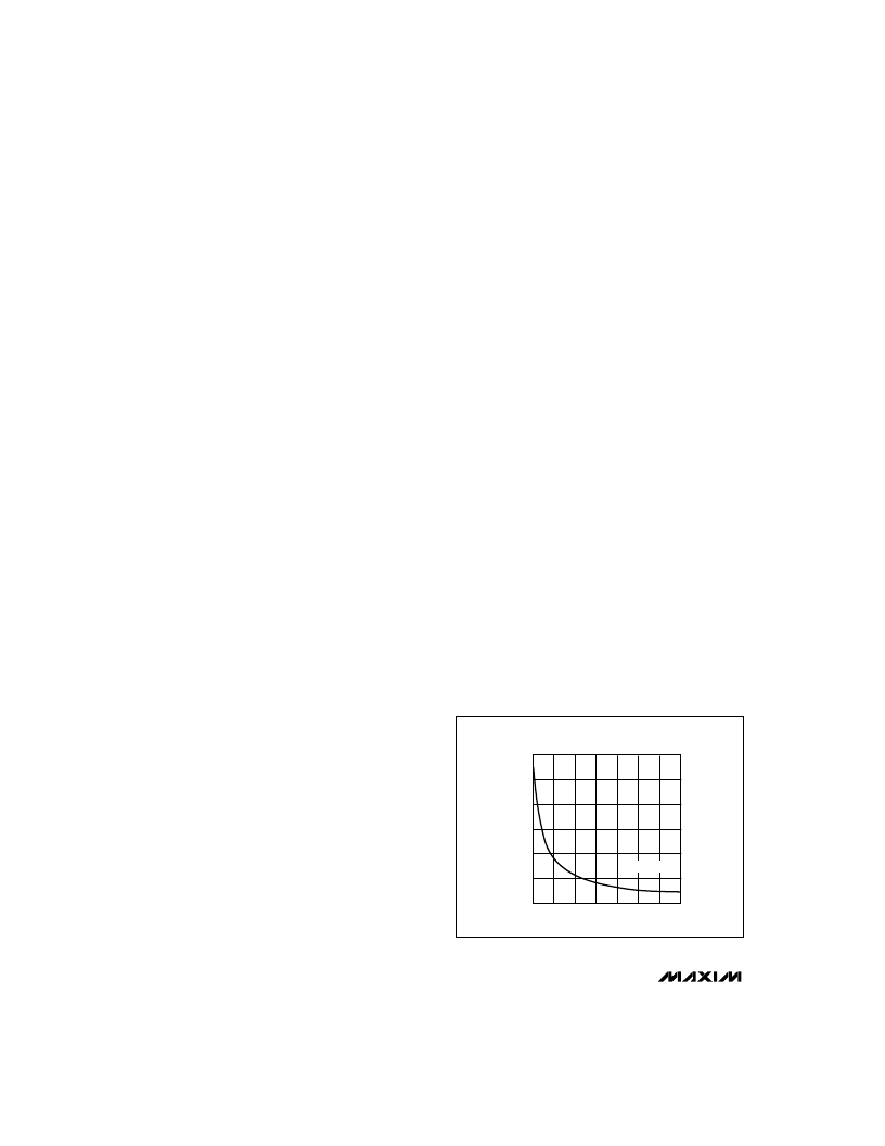
Reduce the MAX777L/MAX778L/MAX779L peak induc-
tor current by connecting a resistor between ILIM and
IN. See Figure 2 to select the resistor.
Low-Voltage Input, 3V /3.3V /5V /
Adjustable Output, S tep-Up DC-DC Converters
8
_______________________________________________________________________________________
600
0
2
8
CURRENT-LIMIT RESISTOR
vs. PEAK INDUCTOR CURRENT
800
M
RESISTOR VALUE (k
)
P1000
1200
4
6
400
0
200
12
14
10
V
IN
= 2.5V
Figure 2. Current-Limit Resistor vs. Current Limit
相關(guān)PDF資料 |
PDF描述 |
|---|---|
| MAX777LCSA | Low-Voltage Input, 3V/3.3V/5V/ Adjustable Output, Step-Up DC-DC Converters |
| MAX778L | Low-Voltage Input, 3V/3.3V/5V/ Adjustable Output, Step-Up DC-DC Converters |
| MAX779L | Low-Voltage Input, 3V/3.3V/5V/ Adjustable Output, Step-Up DC-DC Converters |
| MAX777LEPA | Low-Voltage Input, 3V/3.3V/5V/ Adjustable Output, Step-Up DC-DC Converters |
| MAX777LESA | Low-Voltage Input, 3V/3.3V/5V/ Adjustable Output, Step-Up DC-DC Converters |
相關(guān)代理商/技術(shù)參數(shù) |
參數(shù)描述 |
|---|---|
| MAX777LEPA | 制造商:Rochester Electronics LLC 功能描述: 制造商:Maxim Integrated Products 功能描述: |
| MAX77803EWJ+ | 制造商:Maxim Integrated Products 功能描述:- Rail/Tube |
| MAX77803EWJ+T | 制造商:Maxim Integrated Products 功能描述:- Tape and Reel |
| MAX77803GEWJ+ | 制造商:Maxim Integrated Products 功能描述:- Rail/Tube |
| MAX77803GEWJ+T | 制造商:Maxim Integrated Products 功能描述:- Tape and Reel |
發(fā)布緊急采購,3分鐘左右您將得到回復。