- 您現(xiàn)在的位置:買賣IC網(wǎng) > PDF目錄383451 > MAX6399ATA-T (MAXIM INTEGRATED PRODUCTS INC) High-Voltage, Overvoltage/Undervoltage, Protection Switch Controller PDF資料下載
參數(shù)資料
| 型號: | MAX6399ATA-T |
| 廠商: | MAXIM INTEGRATED PRODUCTS INC |
| 元件分類: | 穩(wěn)壓器 |
| 英文描述: | High-Voltage, Overvoltage/Undervoltage, Protection Switch Controller |
| 中文描述: | SWITCHING CONTROLLER, DSO8 |
| 封裝: | 3 X 3 MM, 0.80 MM HIEGHT, MO229/WEED-3, TDFN-8 |
| 文件頁數(shù): | 7/10頁 |
| 文件大?。?/td> | 649K |
| 代理商: | MAX6399ATA-T |
Monitoring for DC-DC Input
Undervoltage Conditions
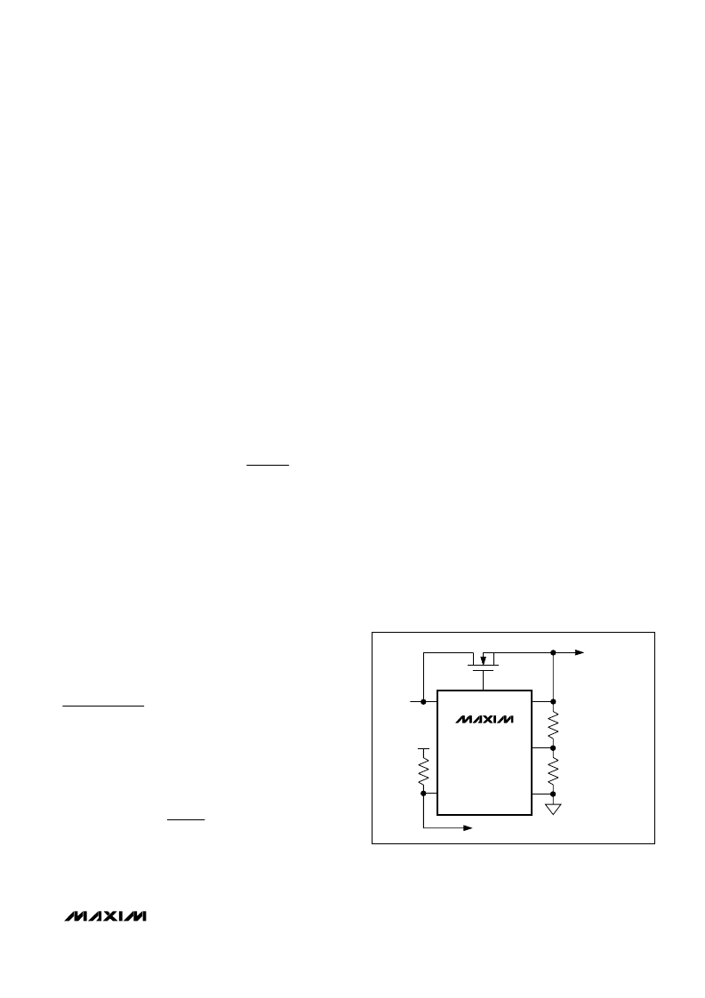
The MAX6399 can be used to monitor for an undervolt-
age condition at the input of a DC-DC converter or
another system voltage by connecting an external resis-
tor-divider at OUT_SET (Figure 4). Use the following
formula to calculate the undervoltage threshold (V
UV
).
Begin by selecting the total end-to-end resistance,
R
TOTAL
= R1 + R2. Choose R
TOTAL
to yield a total cur-
rent equivalent to a minimum 100 x I
SET
(SET’s input
bias current) at the desired overvoltage threshold.
For example, with an undervoltage threshold set to 9V:
R
TOTAL
< 9V/(100 x I
SET
), where I
SET
is SET’s 50nA
input bias current.
R
TOTAL
< 1.8M
Use the following formula to calculate R2:
where V
TH(OUT_SET)
is the 1.23V OUT_SET rising
threshold and V
UV
is the undervoltage condition at the
input of a DC-DC converter.
R2 = 246k
, R
TOTAL
= R2 + R1, where R1 = 1.554M
.
Use a 1.54M
standard resistor.
Using a lower value for total resistance dissipates more
power but provides slightly better accuracy.
Power-OK (POK) Output
POK is an open-drain output that goes low when
OUT_SET falls below its 1.23V (typ) threshold voltage.
Connect a pullup resistor from POK to a supply voltage.
POK asserts high when OUT_SET ramps above 1.23V
typical threshold. POK provides a valid output level
down to V
IN
= 1.5V.
Applications Information
Inrush/Slew-Rate Control
Inrush current control can be implemented by placing a
capacitor at GATE (Figure 5) to slowly ramp up the
GATE, thus limiting the inrush current and controlling
GATE’s slew rate during initial turn-on. The inrush cur-
rent can be approximated using the following formula:
where I
GATE
is GATE’s 100μA sourcing current, I
LOAD
is the load current at the DC-DC output at startup and
C
OUT
is the ouput’s capacitor. However, most DC-DC
converters have soft-start (or peak current limiting)
functions that control inrush current.
Input Overvoltage Protection
The MAX6399 also allows overvoltage protection at the
input supply (see Figure 6). When the programmed
overvoltage threshold is tripped, the internal fast com-
parator turns off the external MOSFET, latching GATE
and OUT low within t
OV
disconnecting the power
source from the load. To unlatch the MAX6399 after an
overvoltage fault, recycle IN or toggle
SHDN
.
Input Transients Clamping
During hot plug-in/unplug, stray inductance in the
power path may cause voltage ringing above the nor-
mal input DC value, which may exceed the MAX6399’s
80V maximum supply rating. An input transient such as
that caused by lightning can also put a severe transient
peak voltage on the input rail. The following techniques
are recommended to reduce the effect of transients:
Minimize stray inductance in the power path using
wide traces, and minimize loop area including the
power traces and the return ground path.
Add a zener diode or transient voltage suppressor
(TVS) rated below the IN absolute maximum rating
(Figure 7).
Add a resistor in series with IN to limit transient cur-
rent going into the input.
I
C
C
I
I
INRUSH
OUT
GATE
GATE
LOAD
×
+
=
R
V
R
V
TH OUT
(
SET
TOTAL
UV
2
×
_
)
=
M
High-Voltage, Overvoltage/Undervoltage,
Protection Switch Controller
_______________________________________________________________________________________
7
MAX6399
GATE
IN
OUT_SET
OUT
GND
POK
R3
R4
3.3V
V
IN
TO DC-DC
ENABLE
TO DC-DC
CONTROLLER
INPUT
Figure 4. Setting the Undervoltage Threshold
相關PDF資料 |
PDF描述 |
|---|---|
| MAX6400BS27-T | Analog IC |
| MAX6400-MAX6405 | レP Supervisory Circuits in 4-Bump (2 x 2) Chip-Scale Package |
| MAX6400 | レP Supervisory Circuits in 4-Bump (2 x 2) Chip-Scale Package |
| MAX6400BS22-T | 1 Microsecond Precision Sample and Hold Amplifier; Temperature Range: 0°C to 70°C; Package: 14-PDIP |
| MAX6400BS23-T | Analog IC |
相關代理商/技術參數(shù) |
參數(shù)描述 |
|---|---|
| MAX639C/D | 功能描述:直流/直流開關轉換器 5V/3.3V/3V Adjustable High-Efficiency Low-IQ Step-Down DC-DC Converters RoHS:否 制造商:STMicroelectronics 最大輸入電壓:4.5 V 開關頻率:1.5 MHz 輸出電壓:4.6 V 輸出電流:250 mA 輸出端數(shù)量:2 最大工作溫度:+ 85 C 安裝風格:SMD/SMT |
| MAX639CPA | 功能描述:直流/直流開關轉換器 5/3.3/3V Adjustable Step-Down RoHS:否 制造商:STMicroelectronics 最大輸入電壓:4.5 V 開關頻率:1.5 MHz 輸出電壓:4.6 V 輸出電流:250 mA 輸出端數(shù)量:2 最大工作溫度:+ 85 C 安裝風格:SMD/SMT |
| MAX639CPA+ | 功能描述:直流/直流開關轉換器 5/3.3/3V Adjustable Step-Down RoHS:否 制造商:STMicroelectronics 最大輸入電壓:4.5 V 開關頻率:1.5 MHz 輸出電壓:4.6 V 輸出電流:250 mA 輸出端數(shù)量:2 最大工作溫度:+ 85 C 安裝風格:SMD/SMT |
| MAX639CSA | 功能描述:直流/直流開關轉換器 5/3.3/3V Adjustable Step-Down RoHS:否 制造商:STMicroelectronics 最大輸入電壓:4.5 V 開關頻率:1.5 MHz 輸出電壓:4.6 V 輸出電流:250 mA 輸出端數(shù)量:2 最大工作溫度:+ 85 C 安裝風格:SMD/SMT |
| MAX639CSA+ | 功能描述:直流/直流開關轉換器 5/3.3/3V Adjustable Step-Down RoHS:否 制造商:STMicroelectronics 最大輸入電壓:4.5 V 開關頻率:1.5 MHz 輸出電壓:4.6 V 輸出電流:250 mA 輸出端數(shù)量:2 最大工作溫度:+ 85 C 安裝風格:SMD/SMT |
發(fā)布緊急采購,3分鐘左右您將得到回復。