- 您現(xiàn)在的位置:買賣IC網(wǎng) > PDF目錄384681 > MAX5038EAI18 (MAXIM INTEGRATED PRODUCTS INC) Dual-Phase, Parallelable, Average Current-Mode Controllers PDF資料下載
參數(shù)資料
| 型號: | MAX5038EAI18 |
| 廠商: | MAXIM INTEGRATED PRODUCTS INC |
| 元件分類: | 穩(wěn)壓器 |
| 英文描述: | Dual-Phase, Parallelable, Average Current-Mode Controllers |
| 中文描述: | SWITCHING CONTROLLER, 525 kHz SWITCHING FREQ-MAX, PDSO28 |
| 封裝: | 5.30 MM, MO150, SSOP-28 |
| 文件頁數(shù): | 9/26頁 |
| 文件大?。?/td> | 406K |
| 代理商: | MAX5038EAI18 |
第1頁第2頁第3頁第4頁第5頁第6頁第7頁第8頁當(dāng)前第9頁第10頁第11頁第12頁第13頁第14頁第15頁第16頁第17頁第18頁第19頁第20頁第21頁第22頁第23頁第24頁第25頁第26頁

M
Dual-Phase, Parallelable, Average Current-Mode
Controllers
_______________________________________________________________________________________
9
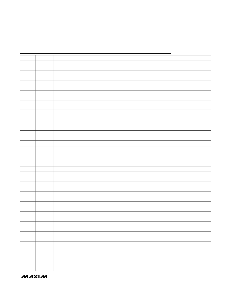
Pin Desc ription
PIN
NAME
FUNCTION
1, 13
CSP2,
CSP1
Current-Sense Differential Amplifier Positive Input. Senses the inductor current. The differential voltage
between CSP_ and CSN_ is amplified internally by the current-sense amplifier gain of 18.
2, 14
CSN2,
CSN1
Current-Sense Differential Amplifier Negative Input. Senses the inductor current.
3
PHASE
Phase-Shift Setting Input. Connect PHASE to V
CC
for 120
°
, leave PHASE unconnected for 90
°
, or connect
PHASE to SGND for 60
°
of phase shift between the rising edges of CLKOUT and CLKIN/DH1.
4
PLLCMP
External Loop-Compensation Input. Connect compensation network for the phase lock loop (see
Phase-
Locked Loop
section).
5, 7
CLP2,
CLP1
Current-Error Amplifier Output. Compensate the current loop by connecting an RC network to ground.
6
SGND
Signal Ground. Ground connection for the internal control circuitry.
8
SENSE+
Differential Output Voltage-Sensing Positive Input. Used to sense a remote load. Connect SENSE+ to
V
OUT+
at the load. The MAX5038 regulates the difference between SENSE+ and SENSE- according to the
factory preset output voltage. The MAX5041 regulates the SENSE+ to SENSE- difference to +1.0V.
9
SENSE-
Differential Output Voltage-Sensing Negative Input. Used to sense a remote load. Connect SENSE- to
V
OUT-
or PGND at the load.
10
DIFF
Differential Remote-Sense Amplifier Output. DIFF is the output of a precision unity-gain amplifier.
11
EAN
Voltage-Error Amplifier Inverting Input. Receives the output of the differential remote-sense amplifier.
Referenced to SGND.
12
EAOUT
Voltage-Error Amplifier Output. Connect to the external gain-setting feedback resistor. The external error
amplifier gain-setting resistors determine the amount of adaptive voltage positioning
15
EN
Output Enable. A logic low shuts down the power drivers. EN has an internal 5μA pullup current.
16, 26
BST1,
BST2
Boost Flying-Capacitor Connection. Reservoir capacitor connection for the high-side FET driver supply.
Connect 0.47μF ceramic capacitors between BST_ and LX_.
17, 25
DH1,
DH2
High-Side Gate Driver Output. Drives the gate of the high-side MOSFET.
18, 24
LX1, LX2
Inductor Connection. Source connection for the high-side MOSFETs. Also serves as the return terminal for
the high-side driver.
19, 23
DL1, DL2
Low-Side Gate Driver Output. Synchronous MOSFET gate drivers for the two phases.
20
V
CC
Internal +5V Regulator Output. V
CC
is derived internally from the IN voltage. Bypass to SGND with 4.7μF
and 0.1μF ceramic capacitors.
21
IN
Supply Voltage Connection. Connect IN to V
CC
for a +5V system. Connect the VRM input to IN through an
RC lowpass filter, a 2.2
resistor and a 0.1μF ceramic capacitor.
22
PGND
Power Ground. Connect PGND, low-side synchronous MOSFET’s source, and V
CC
bypass capacitor
returns together.
27
CLKOUT
Oscillator Output. CLKOUT is phase-shifted from CLKIN by the amount specified by PHASE. Use CLKOUT
to parallel additional MAX5038/MAX5041s.
28
CLKIN
CMOS Logic Clock Input. Drive the internal oscillator with a frequency range between 125kHz and 600kHz.
The PWM frequency defaults to the internal oscillator if CLKIN is connected to V
CC
or SGND. Connect
CLKIN to SGND to set the internal oscillator to 250kHz or connect to V
CC
to set the internal oscillator to
500kHz. CLKIN has an internal 5μA pulldown current.
相關(guān)PDF資料 |
PDF描述 |
|---|---|
| MAX5038 | Dual-Phase, Parallelable, Average Current-Mode Controllers |
| MAX503 | Low Power 5V RS232 Dual Driver/Receiver with 0.1?μF Capacitors; Package: SO; No of Pins: 16; Temperature Range: -40?°C to 85?°C |
| MAX503EWG | 5V, Low-Power, Parallel-Input, Voltage-Output, 10-Bit DAC |
| MAX503CAG | Low Power 5V RS232 Dual Driver/Receiver with 0.1?μF Capacitors; Package: SO; No of Pins: 16; Temperature Range: -40?°C to 85?°C |
| MAX503CNG | Low Power 5V RS232 Dual Driver/Receiver with 0.1?μF Capacitors; Package: SO; No of Pins: 16; Temperature Range: -40?°C to 85?°C |
相關(guān)代理商/技術(shù)參數(shù) |
參數(shù)描述 |
|---|---|
| MAX5038EAI18+ | 制造商:Maxim Integrated Products 功能描述:- Rail/Tube |
| MAX5038EAI18-T | 功能描述:電流型 PWM 控制器 RoHS:否 制造商:Texas Instruments 開關(guān)頻率:27 KHz 上升時間: 下降時間: 工作電源電壓:6 V to 15 V 工作電源電流:1.5 mA 輸出端數(shù)量:1 最大工作溫度:+ 105 C 安裝風(fēng)格:SMD/SMT 封裝 / 箱體:TSSOP-14 |
| MAX5038EAI25 | 功能描述:電流型 PWM 控制器 RoHS:否 制造商:Texas Instruments 開關(guān)頻率:27 KHz 上升時間: 下降時間: 工作電源電壓:6 V to 15 V 工作電源電流:1.5 mA 輸出端數(shù)量:1 最大工作溫度:+ 105 C 安裝風(fēng)格:SMD/SMT 封裝 / 箱體:TSSOP-14 |
| MAX5038EAI25+ | 制造商:Maxim Integrated Products 功能描述:- Rail/Tube |
| MAX5038EAI25-T | 功能描述:電流型 PWM 控制器 RoHS:否 制造商:Texas Instruments 開關(guān)頻率:27 KHz 上升時間: 下降時間: 工作電源電壓:6 V to 15 V 工作電源電流:1.5 mA 輸出端數(shù)量:1 最大工作溫度:+ 105 C 安裝風(fēng)格:SMD/SMT 封裝 / 箱體:TSSOP-14 |
發(fā)布緊急采購,3分鐘左右您將得到回復(fù)。