- 您現(xiàn)在的位置:買賣IC網(wǎng) > PDF目錄384672 > MAX4397SCTM (MAXIM INTEGRATED PRODUCTS INC) Audio/Video Switch For Dual SCART Connectors PDF資料下載
參數(shù)資料
| 型號(hào): | MAX4397SCTM |
| 廠商: | MAXIM INTEGRATED PRODUCTS INC |
| 元件分類: | 運(yùn)動(dòng)控制電子 |
| 英文描述: | Audio/Video Switch For Dual SCART Connectors |
| 中文描述: | DUAL 7-CHANNEL, AUDIO/VIDEO SWITCH, QCC48 |
| 封裝: | 7 X 7 MM, 0.80 MM HEIGHT, MO-220, TQFN-48 |
| 文件頁數(shù): | 10/30頁 |
| 文件大?。?/td> | 834K |
| 代理商: | MAX4397SCTM |
第1頁第2頁第3頁第4頁第5頁第6頁第7頁第8頁第9頁當(dāng)前第10頁第11頁第12頁第13頁第14頁第15頁第16頁第17頁第18頁第19頁第20頁第21頁第22頁第23頁第24頁第25頁第26頁第27頁第28頁第29頁第30頁
M
Audio/Video Switch for Dual SCART Connectors
10
______________________________________________________________________________________
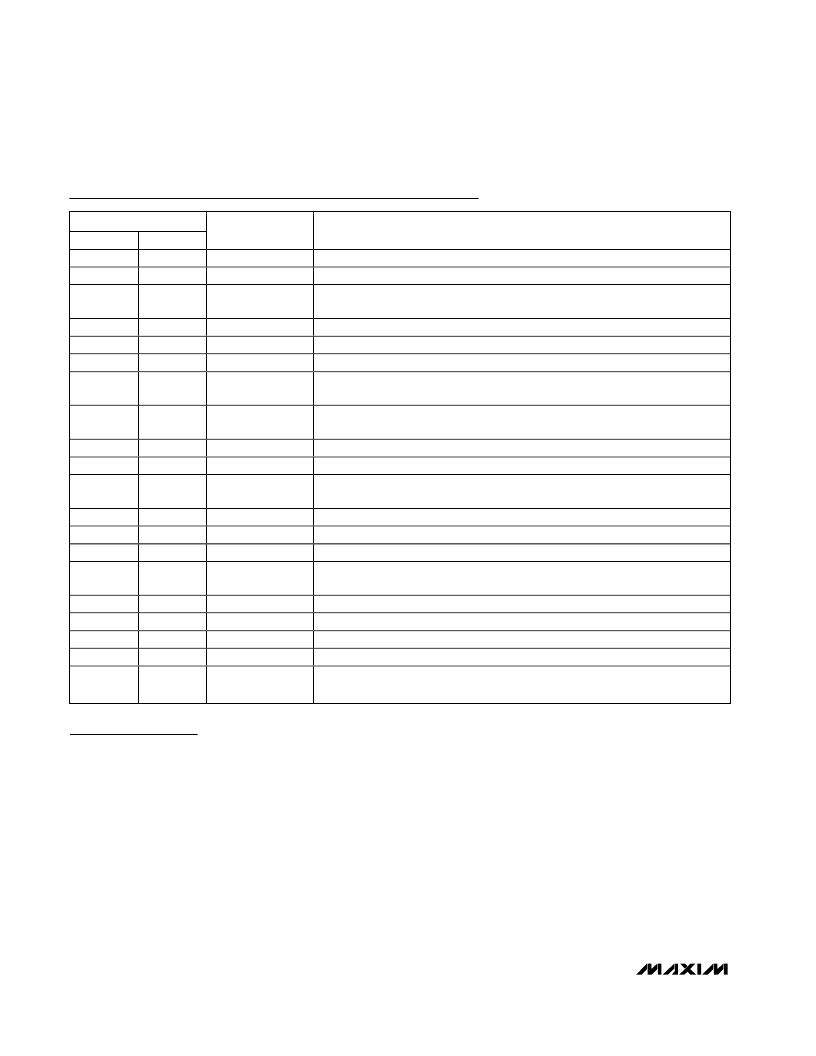
Pin Description (continued)
PIN
MAX4397D
29
30
MAX4397S
29
30
NAME
FUNCTION
RF_CVBS_OUT
TV_Y/CVBS_OUT
RF Modulator Composite Video Output. Internally biased at 1V.
TV SCART Luma/Composite Video Output. Internally biased at 1V.
TV SCART Red/Chroma Video Output. Internally biased at 1V for Red video signal
and 2.2V for Chroma video signal.
TV SCART Green Video Output. Internally biased at 1V.
TV SCART Blue Video Output. Internally biased at 1V.
VCR SCART Luma/Composite Video Output. Internally biased at 1V.
VCR SCART Red/Chroma Video Output. Internally biased at 1V for Red video
signals and 2.2V for Chroma video signal.
31
31
TV_R/C_OUT
32
33
34
32
33
34
TV_G_OUT
TV_B_OUT
VCR_Y/CVBS_OUT
35
35
VCR_R/C_OUT
37
37
TV_R/C_IN
TV SCART Red/Chroma Video Input. Internally biased at 1.2V for Red video
signals, or 1.9V for Chroma video signals.
TV SCART Luma/Composite Video Input. Internally biased at 1.2V.
VCR SCART Luma/Composite Video Input. Internally biased at 1.2V.
38
39
38
39
TV_Y/CVBS_IN
VCR_Y/CVBS_IN
40
40
VCR_R/C_IN
VCR SCART Red/Chroma Video Input. Internally biased at 1.2V for Red video
signals and 1.9V for Chroma video signals.
VCR SCART Green Video Input. Internally biased at 1.2V.
VCR SCART Blue Video Input. Internally biased at 1.2V.
Digital Encoder Luma/Composite Video Input. Internally biased at 1.2V.
41
42
43
41
42
43
VCR_G_IN
VCR_B_IN
ENC_Y/CVBS_IN
44
44
ENC_R/C_IN
Digital Encoder Red/Chroma Video Input. Internally biased at 1.2V for Red video
signals, or 1.9V for Chroma video signals.
Digital Encoder Green Video Input. Internally biased at 1.2V.
Digital Encoder Blue Video Input. Internally biased at 1.2V.
Digital Encoder Luma Video Input. Internally biased at 1.2V.
Digital Encoder Chroma Video Input. Internally biased at 1.9V.
Exposed Paddle. Solder to the circuit board ground (GNDAUD) for proper thermal
and electrical performance.
45
46
47
48
45
46
47
48
ENC_G_IN
ENC_B_IN
ENC_Y_IN
ENC_C_IN
EP
EP
GNDAUD
Detailed Description
The MAX4397 is a switch matrix that routes audio and
video signals between different ports using the I
2
C
interface. The ports consist of the MPEG decoder out-
put, and two SCART connectors for the TV and VCR.
Per EN50049 and IEC 933, the encoder can only input
a signal to the SCART connector, while TV and VCR
SCART connectors are bidirectional.
The MAX4397 circuitry consists of four major sections:
the video section, the audio section, the slow- and fast-
switching section, and the digital interface.
The video section consists of clamp and bias circuitry,
input buffers, reconstruction filters, a switch matrix, a
Y/C mixer, and output buffers. All video inputs are AC-
coupled through a 0.1μF capacitor to set an acceptable
DC level using clamp or bias networks. The bidirection-
al Red/Chroma outputs can be connected to ground
using I
2
C control to make them terminations when
Red/Chroma is an input (see the
Video Inputs
section).
The audio section features an input buffer, a switching
matrix, volume- or gain-control circuitry, and output dri-
vers. The audio inputs are AC-coupled through a 0.1μF
capacitor. Only the audio encoder inputs of the
MAX4397D are different from the MAX4397S. The
MAX4397S has a single-ended audio encoder input
while the audio encoder input for the MAX4397D is dif-
ferential. The TV output audio path has volume control
from -56dB to +6dB in 2dB steps, while the VCR output
audio path has volume control from -6dB to +6dB in
6dB steps. The MAX4397 can be configured to switch
inputs during a zero-crossing function to reduce clicks.
相關(guān)PDF資料 |
PDF描述 |
|---|---|
| MAX4427ESA | Dual High-Speed 1.5A MOSFET Drivers |
| MAX4428MJA | Dual High-Speed 1.5A MOSFET Drivers |
| MAX4427CPA | Dual High-Speed 1.5A MOSFET Drivers |
| MAX4427CSA | Dual High-Speed 1.5A MOSFET Drivers |
| MAX4428CSA | Dual High-Speed 1.5A MOSFET Drivers |
相關(guān)代理商/技術(shù)參數(shù) |
參數(shù)描述 |
|---|---|
| MAX4397SCTM+ | 功能描述:視頻開關(guān) IC Audio/Video Switch for Dual SCART Con RoHS:否 制造商:Texas Instruments 開關(guān)數(shù)量:4 開啟電阻(最大值):12 Ohms 傳播延遲時(shí)間: 開啟時(shí)間(最大值): 關(guān)閉時(shí)間(最大值): 最大工作溫度:+ 85 C 最小工作溫度:- 40 C 封裝 / 箱體:WQFN-42 封裝:Reel |
| MAX4397SCTM+T | 功能描述:視頻開關(guān) IC Audio/Video Switch for Dual SCART Con RoHS:否 制造商:Texas Instruments 開關(guān)數(shù)量:4 開啟電阻(最大值):12 Ohms 傳播延遲時(shí)間: 開啟時(shí)間(最大值): 關(guān)閉時(shí)間(最大值): 最大工作溫度:+ 85 C 最小工作溫度:- 40 C 封裝 / 箱體:WQFN-42 封裝:Reel |
| MAX4397SCTM-T | 功能描述:視頻開關(guān) IC RoHS:否 制造商:Texas Instruments 開關(guān)數(shù)量:4 開啟電阻(最大值):12 Ohms 傳播延遲時(shí)間: 開啟時(shí)間(最大值): 關(guān)閉時(shí)間(最大值): 最大工作溫度:+ 85 C 最小工作溫度:- 40 C 封裝 / 箱體:WQFN-42 封裝:Reel |
| MAX4399CTK | 功能描述:視頻開關(guān) IC RoHS:否 制造商:Texas Instruments 開關(guān)數(shù)量:4 開啟電阻(最大值):12 Ohms 傳播延遲時(shí)間: 開啟時(shí)間(最大值): 關(guān)閉時(shí)間(最大值): 最大工作溫度:+ 85 C 最小工作溫度:- 40 C 封裝 / 箱體:WQFN-42 封裝:Reel |
| MAX4399CTK+ | 功能描述:視頻開關(guān) IC Audio/Video Switch for 3 SCART Con RoHS:否 制造商:Texas Instruments 開關(guān)數(shù)量:4 開啟電阻(最大值):12 Ohms 傳播延遲時(shí)間: 開啟時(shí)間(最大值): 關(guān)閉時(shí)間(最大值): 最大工作溫度:+ 85 C 最小工作溫度:- 40 C 封裝 / 箱體:WQFN-42 封裝:Reel |
發(fā)布緊急采購(gòu),3分鐘左右您將得到回復(fù)。