- 您現在的位置:買賣IC網 > PDF目錄385524 > MAX2385EBP-T (MAXIM INTEGRATED PRODUCTS INC) CDMA + GPS LNA/Mixers PDF資料下載
參數資料
| 型號: | MAX2385EBP-T |
| 廠商: | MAXIM INTEGRATED PRODUCTS INC |
| 元件分類: | 無繩電話/電話 |
| 英文描述: | CDMA + GPS LNA/Mixers |
| 中文描述: | TELECOM, CELLULAR, RF AND BASEBAND CIRCUIT, PBGA20 |
| 封裝: | 2.10 X 2.70 MM, UCSP-20 |
| 文件頁數: | 2/18頁 |
| 文件大小: | 216K |
| 代理商: | MAX2385EBP-T |
M
CDMA + GPS LNA/Mixers
2
_______________________________________________________________________________________
ABSOLUTE MAXIMUM RATINGS
V
CC
to GND...........................................................-0.3V to +4.3V
Digital Input Voltage to GND ........................-0.3V to V
CC
+ 0.3V
RF Input Power...............................................................+12dBm
Digital Input Current .........................................................±10mA
Continuous Power Dissipation
5
4 UCSP (T
A
= +70
°
C, derate 1.2mW/
°
C above
T
A
= +70
°
C) .................................................................995mW
Stresses beyond those listed under “Absolute Maximum Ratings” may cause permanent damage to the device. These are stress ratings only, and functional
operation of the device at these or any other conditions beyond those indicated in the operational sections of the specifications is not implied. Exposure to
absolute maximum rating conditions for extended periods may affect device reliability.
Thermal Resistance from Junction to Ambient..............+80
°
C/W
Operating Temperature Range ...........................-40
°
C to +85
°
C
Junction Temperature......................................................+150
°
C
Storage Temperature Range.............................-65
°
C to +150
°
C
Bump Temperature (Soldering) (Note 1)
Infrared (15s) ...............................................................+220
°
C
Vapor Phase (60s) .......................................................+215
°
C
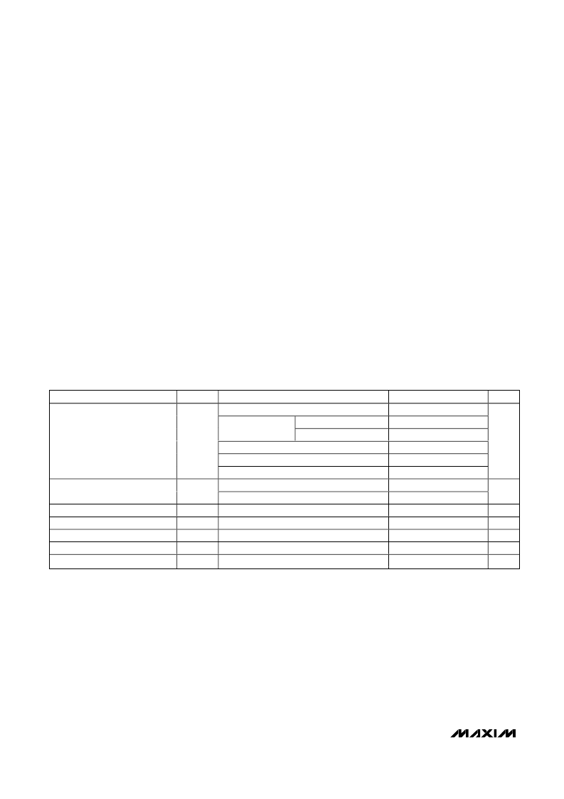
DC ELECTRICAL CHARACTERISTICS
(V
CC
= +2.7 to +3.6V, R
BIAS
= 47k
, V
IH
= +2.0V, V
IL
= +0.6V, T
A
= -40
°
C to +85
°
C. Typical values are at +2.75V and T
A
= +25
°
C,
unless otherwise noted.) (Note 2) (Table 1)
PARAMETER
SYMBOL
CONDITIONS
MIN
TYP
3.7
6.5
8.3
10.2
12.5
17.4
9.6
16.9
0.1
MAX
4.5
7.6
9.7
11.8
15.0
20.9
11.6
22.3
10
U N T S
ULG mode
R
BIAS
= 47k
R
BIAS
= 36k
(Note 3)
LG mode
MG mode
HGLL
HGHL
MAX2385
MAX2386
SHDN mode
CDMA Active Supply Current
I
CC
mA
GPS Active Supply Current
I
CC
mA
Shutdown Supply Current
Digital Input Logic High
Digital Input Logic Low
Digital Input Current
Additional Current for LO Buffer
I
CC
V
IH
V
IL
μA
V
V
μA
mA
2.0
0.6
25
7.3
-25
BUFFEN = high
5.2
Note 1:
This device is constructed using a unique set of packaging techniques that impose a limit on the thermal profile the device
can be exposed to during board level solder attach and rework. This limit permits only the use of the solder profiles recom-
mended in the industry standard specification, JEDEC 020A, paragraph 7.6, Table 3 for IR/VPR and convection reflow.
Preheating is required. Hand or wave soldering is not recommended.
相關PDF資料 |
PDF描述 |
|---|---|
| MAX2386EBP-T | CDMA + GPS LNA/Mixers |
| MAX2394 | MAX2394/MAX2395 Evaluation Kits |
| MAX2395 | MAX2394/MAX2395 Evaluation Kits |
| MAX2396 | Evaluation Kit |
| MAX2402EVKIT-SO | Evaluation Kit |
相關代理商/技術參數 |
參數描述 |
|---|---|
| MAX2385EVKIT | 功能描述:射頻開發(fā)工具 RoHS:否 制造商:Taiyo Yuden 產品:Wireless Modules 類型:Wireless Audio 工具用于評估:WYSAAVDX7 頻率: 工作電源電壓:3.4 V to 5.5 V |
| MAX2386EBP | 制造商:Maxim Integrated Products 功能描述:CDMA + GPS LNA/MIXERS - Rail/Tube |
| MAX2386EBP-T | 功能描述:射頻混合器 RoHS:否 制造商:NXP Semiconductors 頻率范圍: 轉換損失——最大: 工作電源電壓:6 V 最大工作溫度:+ 85 C 最小工作溫度:- 40 C 安裝風格:Through Hole 封裝 / 箱體:PDIP-8 封裝:Tube |
| MAX2386EVKIT | 功能描述:射頻開發(fā)工具 RoHS:否 制造商:Taiyo Yuden 產品:Wireless Modules 類型:Wireless Audio 工具用于評估:WYSAAVDX7 頻率: 工作電源電壓:3.4 V to 5.5 V |
| MAX2387EGC | 功能描述:射頻混合器 RoHS:否 制造商:NXP Semiconductors 頻率范圍: 轉換損失——最大: 工作電源電壓:6 V 最大工作溫度:+ 85 C 最小工作溫度:- 40 C 安裝風格:Through Hole 封裝 / 箱體:PDIP-8 封裝:Tube |
發(fā)布緊急采購,3分鐘左右您將得到回復。