- 您現(xiàn)在的位置:買賣IC網(wǎng) > PDF目錄384654 > MAX1822 (Maxim Integrated Products, Inc.) High-Side Power Supply PDF資料下載
參數(shù)資料
| 型號: | MAX1822 |
| 廠商: | Maxim Integrated Products, Inc. |
| 英文描述: | High-Side Power Supply |
| 中文描述: | 高端電源 |
| 文件頁數(shù): | 7/10頁 |
| 文件大小: | 173K |
| 代理商: | MAX1822 |
internal switches during charge-pump cycles. This may
damage the device.
Output Protection
The MAX1822 is not internally short-circuit protected. In
applications where the output is susceptible to short
circuit, external output short-circuit protection must be
provided. Accomplish this by connecting a resistor
between V
OUT
and the load to limit output current to
less than 25mA. The resistor value is determined by the
following formula:
Typical Applications
One MAX1822 Drives
Six High-Side Switches
Multiple subsystems or modules can be turned on and
off using a single MAX1822 and an open-drain hex
buffer such as the 74C906 (
Figure 3). The drains of all
buffer outputs are pulled through resistors to the
MAX1822
’
s V
OUT
. The pullup resistance depends on
the number of channels being used with the MAX1822
and power-dissipation limitations. The minimum pullup
resistor value is determined by the number of channels
paralleled on each high-side power supply and the
high-side output current from the MAX1822 at a given
supply voltage, calculated as follows:
where V
OUT
is the high-side output voltage and I
OUT
is
the output current of the MAX1822.
For example, assuming an output current of 1mA and
six channels, as in Figure 3, the minimum pullup resis-
tor value that will not excessively load the MAX1822 is
about 100k
, assuming all six channels are pulled low
at the same time. The value of the pullup resistor also
affects the turn-on time of each FET, and hence the
amount of energy dissipated in the FET during turn-on.
The rate of rise of V
GS
is limited by the RC time con-
stant of the pullup resistor and FET gate capacitance;
waste power will be dissipated in the FET equal to
(I
LOAD
)
2
x r
DS
during the RC time period.
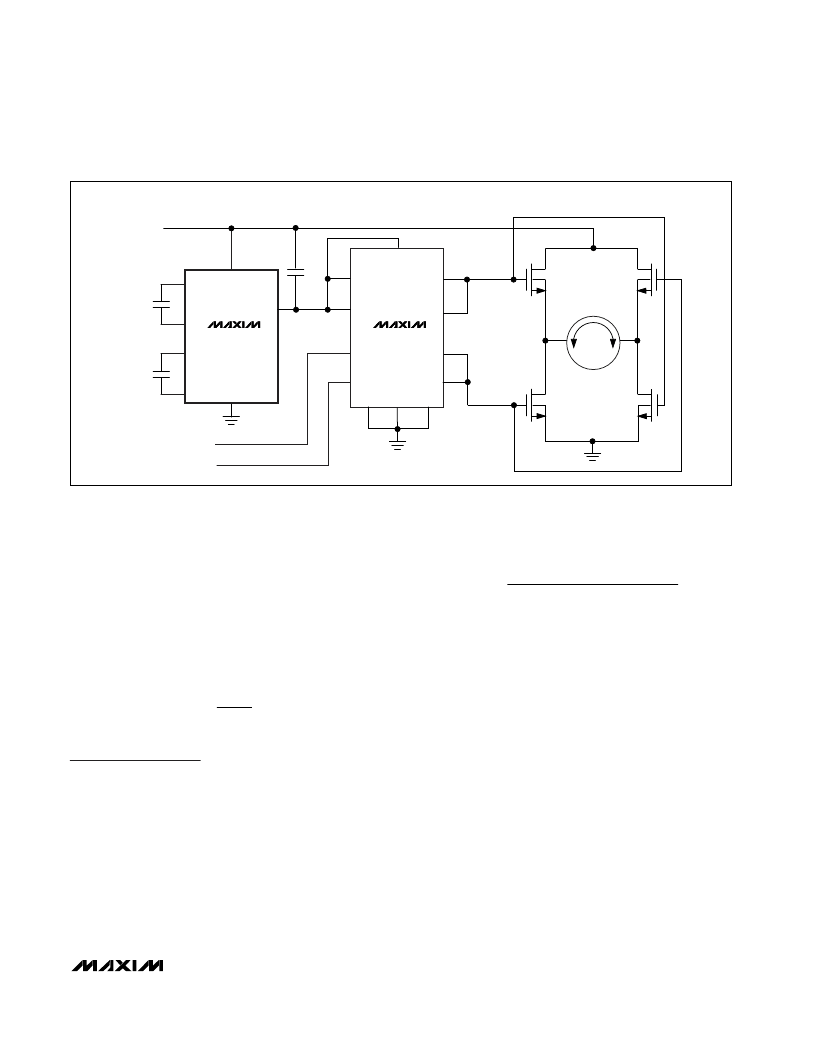
H-Bridge Motor Driver
An H-bridge motor driver is shown in Figure 4. The
motor direction can be controlled by toggling between
IN1 and IN2 of the DG303 analog switch. Each switch
section turns on the appropriate FET pair, which pass-
es current through the motor in the desired direction.
R
V
I
OUT
MIN
OUT
=
x number of channels
)
R
V
mA
CL
CC
≥
25
M
High-Side Power Supply
_______________________________________________________________________________________
7
Figure 4. H-Bridge Motor Controller
MAX1822
DG303
C1
1
+5V
7
C1
0.047
μ
F
C3
10
μ
F
H-BRIDGE MOTOR CONTROL
C2
0.047
μ
F
6
2
4
REVERSE
FORWARD
5
V+
6
9
7
3
12
11
10
IRF541
IRF541
IRF541
IRF541
13
+
–
5
4
D1
D2
IN1
IN2
S1
S4
DC MOTOR
+5V
S2
S3
GND
D3
D4
8
C1-
C2+
C2-
GND
V
CC
V
OUT
14
相關PDF資料 |
PDF描述 |
|---|---|
| MAX1822ESA | High-Side Power Supply |
| MAX1823 | Dual USB Switch with Fault Blanking and Autoreset |
| MAX1823AEUB | Replaced by TMS320BC52 : |
| MAX1823BEUB | Replaced by TMS320BC52 : |
| MAX1823EUB | Replaced by TMS320BC52 : Digital Signal Processors 100-LQFP |
相關代理商/技術參數(shù) |
參數(shù)描述 |
|---|---|
| MAX1822EPA | 功能描述:直流/直流開關調節(jié)器 High-Side Power Supply RoHS:否 制造商:International Rectifier 最大輸入電壓:21 V 開關頻率:1.5 MHz 輸出電壓:0.5 V to 0.86 V 輸出電流:4 A 輸出端數(shù)量: 最大工作溫度: 安裝風格:SMD/SMT 封裝 / 箱體:PQFN 4 x 5 |
| MAX1822EPA+ | 功能描述:直流/直流開關調節(jié)器 High-Side Power Supply RoHS:否 制造商:International Rectifier 最大輸入電壓:21 V 開關頻率:1.5 MHz 輸出電壓:0.5 V to 0.86 V 輸出電流:4 A 輸出端數(shù)量: 最大工作溫度: 安裝風格:SMD/SMT 封裝 / 箱體:PQFN 4 x 5 |
| MAX1822ESA | 功能描述:直流/直流開關調節(jié)器 High-Side Power Supply RoHS:否 制造商:International Rectifier 最大輸入電壓:21 V 開關頻率:1.5 MHz 輸出電壓:0.5 V to 0.86 V 輸出電流:4 A 輸出端數(shù)量: 最大工作溫度: 安裝風格:SMD/SMT 封裝 / 箱體:PQFN 4 x 5 |
| MAX1822ESA+ | 功能描述:直流/直流開關調節(jié)器 High-Side Power Supply RoHS:否 制造商:International Rectifier 最大輸入電壓:21 V 開關頻率:1.5 MHz 輸出電壓:0.5 V to 0.86 V 輸出電流:4 A 輸出端數(shù)量: 最大工作溫度: 安裝風格:SMD/SMT 封裝 / 箱體:PQFN 4 x 5 |
| MAX1822ESA+T | 功能描述:直流/直流開關調節(jié)器 High-Side Power Supply RoHS:否 制造商:International Rectifier 最大輸入電壓:21 V 開關頻率:1.5 MHz 輸出電壓:0.5 V to 0.86 V 輸出電流:4 A 輸出端數(shù)量: 最大工作溫度: 安裝風格:SMD/SMT 封裝 / 箱體:PQFN 4 x 5 |
發(fā)布緊急采購,3分鐘左右您將得到回復。