- 您現(xiàn)在的位置:買賣IC網(wǎng) > PDF目錄11817 > MAX14830ETM+T (Maxim Integrated Products)IC UART PDF資料下載
參數(shù)資料
| 型號(hào): | MAX14830ETM+T |
| 廠商: | Maxim Integrated Products |
| 文件頁數(shù): | 60/68頁 |
| 文件大小: | 0K |
| 描述: | IC UART |
| 產(chǎn)品培訓(xùn)模塊: | Obsolescence Mitigation Program |
| 標(biāo)準(zhǔn)包裝: | 2,500 |
| 系列: | * |
第1頁第2頁第3頁第4頁第5頁第6頁第7頁第8頁第9頁第10頁第11頁第12頁第13頁第14頁第15頁第16頁第17頁第18頁第19頁第20頁第21頁第22頁第23頁第24頁第25頁第26頁第27頁第28頁第29頁第30頁第31頁第32頁第33頁第34頁第35頁第36頁第37頁第38頁第39頁第40頁第41頁第42頁第43頁第44頁第45頁第46頁第47頁第48頁第49頁第50頁第51頁第52頁第53頁第54頁第55頁第56頁第57頁第58頁第59頁當(dāng)前第60頁第61頁第62頁第63頁第64頁第65頁第66頁第67頁第68頁

63
Maxim Integrated
Quad Serial UART with 128-Word FIFOs
MAX14830
Acknowledge Bits
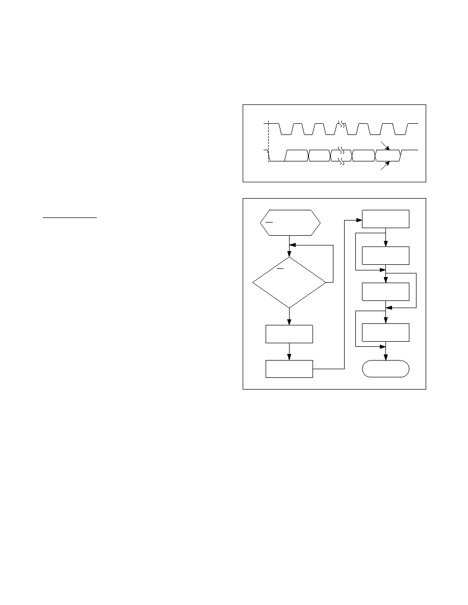
Data transfers are acknowledged with an acknowledge
bit (ACK) or a not-acknowledge bit (NACK). Both the
master and the MAX14830 generate ACK bits. To gener-
ate an ACK, pull SDA low before the rising edge of the
ninth clock pulse and keep it low during the high period
of the ninth clock pulse (Figure 26). To generate a NACK,
leave SDA high before the rising edge of the ninth clock
pulse and keep it high for the duration of the ninth clock
pulse. Monitoring for NACK bits allows for detection of
unsuccessful data transfers.
Applications Information
Startup and Initialization
The MAX14830 is initialized following power-up or a
hardware or software reset (Figure 27). Check that the
MAX14830 is ready for operation after a power-up or
reset by monitoring the IRQ output, if interrupt driven
operation is employed.
In polled mode, repeatedly read a known register until
the expected contents are returned.
Low-Power Operation
To reduce the power consumption during normal opera-
tion, the following techniques can be adopted:
DonotusetheinternalPLL.Thissavesthemostpower
of the options listed here. Disable and bypass the PLL.
WhenanyofthefourUARTsarenotbeingused,sop
clicking via CLKDisabl.
Use an external 1.8V supply at V18. This saves the
power dissipated in the internal 1.8V linear regulator
for the 1.8V core supply. Disable the internal regulator
by connecting LDOEN to DGND.
Keepinternalclockratesaslowaspossible.
UsealowvoltageontheVA supply.
Interrupts and Polling
Monitor the MAX14830 by polling the ISR register or
by monitoring the IRQ output. In polled mode, the IRQ
physical interrupt output is not used and the host control-
ler polls the ISR register at frequent intervals to establish
the state of the MAX14830.
Alternatively, the physical interrupt, IRQ, of the MAX14830
can be used to interrupt the host controller at specified
events, making polling unnecessary. The IRQ output is
an open-drain output that requires a pullup resistor to VL.
Logic-Level Translation
The MAX14830 can be directly connected to transceivers
and controllers that have different supply voltages. The VL
input defines the logic voltage levels of the controller inter-
face while the VEXT voltage defines the logic of the trans-
ceiver interface. This ensures flexibility when selecting a
controller and transceiver. Figure 28 is an example of a
setup when the controller, transceiver, and the MAX14830
are powered by three different supplies.
IO-Link Application
The Typical Operating Circuit shows a four-part IO-link
master circuit with SPI control on the MAX14830 and the
IO-link transceivers.
Figure 26. Acknowledge Bits
Figure 27. Startup and Initialization Flow Chart
NOT ACKNOWLEDGE
ACKNOWLEDGE
12
89
SDA
SCL
S
POWER-UP/
RST INPUT PULLED HIGH
CONFIGURE
CLOCKING
YES
NO
CONFIGURE
FIFO CONTROL
CONFIGURE
FLOW CONTROL
CONFIGURE
GPIOs
START
COMMUNICATION
CONFIGURE
MODES
IRQ IS HIGH?
OR
DIVLSB READ
SUCCESSFULLY?
ENABLE
INTERRUPTS
相關(guān)PDF資料 |
PDF描述 |
|---|---|
| V24C12H150BL3 | CONVERTER MOD DC/DC 12V 150W |
| MAX3111EEWI+TG36 | IC UART SPI COMPAT 28-SOIC |
| MAX3100ETG+ | IC UART SPI/MICROWIRE 24-TQFN-EP |
| MAX3140EEI+T | IC UART W/RS485 28-QSOP |
| MAX3110EEWI+TG36 | IC UART SPI COMPAT 28-SOIC |
相關(guān)代理商/技術(shù)參數(shù) |
參數(shù)描述 |
|---|---|
| MAX14830EVKIT# | 功能描述:界面開發(fā)工具 MAX14830 Eval Kit RoHS:否 制造商:Bourns 產(chǎn)品:Evaluation Boards 類型:RS-485 工具用于評(píng)估:ADM3485E 接口類型:RS-485 工作電源電壓:3.3 V |
| MAX14830EVKIT+ | 制造商:Maxim Integrated Products 功能描述:QUAD UART EV-KIT WITH IO-LINK AND MULTIPROTOCOL - Boxed Product (Development Kits) |
| MAX1483C/D+ | 功能描述:RS-485接口IC low-power transceivers for RS-485 and RS-422 communication RoHS:否 制造商:Texas Instruments 數(shù)據(jù)速率:250 Kbps 工作電源電壓:3.3 V 電源電流:750 uA 工作溫度范圍:- 40 C to + 125 C 安裝風(fēng)格:SMD/SMT 封裝 / 箱體:SOIC-8 封裝:Tube |
| MAX1483CPA | 功能描述:RS-485接口IC RoHS:否 制造商:Texas Instruments 數(shù)據(jù)速率:250 Kbps 工作電源電壓:3.3 V 電源電流:750 uA 工作溫度范圍:- 40 C to + 125 C 安裝風(fēng)格:SMD/SMT 封裝 / 箱體:SOIC-8 封裝:Tube |
| MAX1483CPA+ | 功能描述:RS-422/RS-485 接口 IC Slew-Rate-Limited RS-485 Transceivers RoHS:否 制造商:Maxim Integrated 數(shù)據(jù)速率:1136 Kbps 工作電源電壓:3 V to 5.5 V 電源電流:5.9 mA 工作溫度范圍:- 40 C to + 85 C 安裝風(fēng)格:SMD/SMT 封裝 / 箱體:SOIC-28 封裝:Tube |
發(fā)布緊急采購,3分鐘左右您將得到回復(fù)。