- 您現(xiàn)在的位置:買賣IC網(wǎng) > PDF目錄370992 > M66242FP (Mitsubishi Electric Corporation) 4-CH 12-BIT PWM GENERATOR PDF資料下載
參數(shù)資料
| 型號: | M66242FP |
| 廠商: | Mitsubishi Electric Corporation |
| 英文描述: | 4-CH 12-BIT PWM GENERATOR |
| 中文描述: | 4通道12位PWM發(fā)生器 |
| 文件頁數(shù): | 1/10頁 |
| 文件大?。?/td> | 109K |
| 代理商: | M66242FP |
1
M66242P/FP
4-4-CH 12-BIT PWM GENERATOR
MIMITSUBISHI
DIDIGITAL ASSP
DESCRIPTION
M66242 Integrated Circuit has four 12-bit PWM (pulse width
modulation) circuits which are built by using the CMOS
(complementary metal oxide semiconductor) process.
This IC controls PWM waveform by adjusting the “H” width
according to serial data sent from MCU (micro controller unit)
or other device. Each channel can be independently con-
trolled.
High-resolution digital-analog converter can be formed eas-
ily by connecting a low-pass filter circuit to the output pins of
this circuit.
FEATURES
Built-in four 12-bit high-resolution pulse width modulation
circuits
Easy digital-analog conversion – Quick output waveform
smoothing
Control by 1.22mV possible per step (V
CC
=5V)
Serial data input
“H” level width setting type
4 independently controlled channels
All 4 channels reset by reset input (R) High-impedance sta-
tus after reset
All 4 channels controlled by output control input (OC)
Settings take effect after ongoing cycle is completed
Input: TTL level
Output: CMOS 3-state output
Output current I
O
=
±
4mA
V
CC
=5V
±
10%
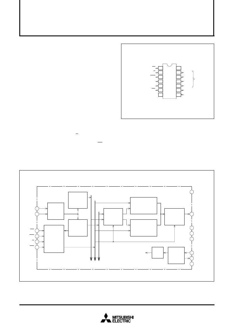
PIN CONFIGURATION (TOP VIEW)
APPLICATION
Analog signal control in televisions and audio systems
Control of lamps, heaters and motors
For software servo in home appliances and industrial ma-
chinery
BLOCK DIAGRAM (EACH CHANNEL)
1
2
3
4
5
6
7
14
13
12
11
10
9
8
CS
R
WR
S
IN
S
CLK
OC
GND
V
CC
PWM1
PWM2
PWM3
PWM4
X
OUT
X
IN
Outline
M
CLOCK OUTPUT
CLOCK INPUT
CHIP SELECT
RESET
WRITE CONTROL
SERIAL DATA INPUT
WRITE CLOCK
OUTPUT CONTROL
OUTPUT
14P4
14P2N-A
4
5
1
2
3
6
7
9
8
10
11
12
13
14
Input
register
Control
circuit
Lower byte
register
Upper byte
register
PWM
register
8-BIT
PWM circuit
4-bit-rate
multiplier
12-bit
PWM circuit
To other channels
1/2
divider
Oscillation
circuit
S
IN
S
CLK
CS
R
WR
OC
GND
X
OUT
X
IN
PWM4
PWM3
PWM2
PWM1
V
CC
相關PDF資料 |
PDF描述 |
|---|---|
| M66242P | 4-CH 12-BIT PWM GENERATOR |
| M66244FP | High Speed Monolithic Pulse Width Modulator |
| M66250 | 5120 X 8-BIT LINE MEMORY(FIFO/LIFO) |
| M66250FP | 5120 X 8-BIT LINE MEMORY(FIFO/LIFO) |
| M66250P | 5120 X 8-BIT LINE MEMORY(FIFO/LIFO) |
相關代理商/技術參數(shù) |
參數(shù)描述 |
|---|---|
| M66242P | 制造商:Renesas Electronics Corporation 功能描述: |
| M66244FP | 制造商:MITSUBISHI 制造商全稱:Mitsubishi Electric Semiconductor 功能描述:High Speed Monolithic Pulse Width Modulator |
| M66250 | 制造商:MITSUBISHI 制造商全稱:Mitsubishi Electric Semiconductor 功能描述:5120 X 8-BIT LINE MEMORY(FIFO/LIFO) |
| M66250FP | 制造商:RENESAS 制造商全稱:Renesas Technology Corp 功能描述:5120*8-BIT LINE MEMORY(FIFO/LIFO) |
| M66250P | 制造商:RENESAS 制造商全稱:Renesas Technology Corp 功能描述:5120*8-BIT LINE MEMORY(FIFO/LIFO) |
發(fā)布緊急采購,3分鐘左右您將得到回復。