- 您現(xiàn)在的位置:買賣IC網(wǎng) > PDF目錄370934 > M38273ECMXXXHP (Mitsubishi Electric Corporation) SINGLE-CHIP 8-BIT CMOS MICROCOMPUTER PDF資料下載
參數(shù)資料
| 型號: | M38273ECMXXXHP |
| 廠商: | Mitsubishi Electric Corporation |
| 英文描述: | SINGLE-CHIP 8-BIT CMOS MICROCOMPUTER |
| 中文描述: | 單芯片8位CMOS微機(jī) |
| 文件頁數(shù): | 21/70頁 |
| 文件大小: | 1112K |
| 代理商: | M38273ECMXXXHP |
第1頁第2頁第3頁第4頁第5頁第6頁第7頁第8頁第9頁第10頁第11頁第12頁第13頁第14頁第15頁第16頁第17頁第18頁第19頁第20頁當(dāng)前第21頁第22頁第23頁第24頁第25頁第26頁第27頁第28頁第29頁第30頁第31頁第32頁第33頁第34頁第35頁第36頁第37頁第38頁第39頁第40頁第41頁第42頁第43頁第44頁第45頁第46頁第47頁第48頁第49頁第50頁第51頁第52頁第53頁第54頁第55頁第56頁第57頁第58頁第59頁第60頁第61頁第62頁第63頁第64頁第65頁第66頁第67頁第68頁第69頁第70頁
21
SINGLE-CHIP 8-BIT CMOS MICROCOMPUTER
MITSUBISHI MICROCOMPUTERS
3827 Group
CNTR
active
edge switch bit
Timer 1 count source
selection bit
Real time port
control bit “0”
“1”
P5
5
/CNTR
1
“0”
f(X
IN
)/16
(f(X
CIN
)
16 in
φ
= X
CIN
divided by 2)
1
active
CNTR
“10”
Timer Y stop
control bit
Timer Y (low) latch (8)
Falling edge detection
Period
Timer Y
interrupt
request
Pulse width HL continuously measurement mode
Rising edge detection
“00”,“01”,“11”
Timer Y operating
mode bit
Timer X
interrupt
request
Timer X mode register
write signal
P5
4
/CNTR
0
Q
Q
T
S
P5
4
direction register
Pulse output mode
P5
4
latch
Timer X stop
control bit
“0”
“1”
Timer X write
control bit
Q D
Latch
Q D
Latch
“1”
“0”
“1”
“10”
Timer X operat-
ing mode bits
“00”,“01”,“11”
f(X
IN
)/16
(f(X
IN
)/16 in low-speed mode
8
)
Pulse width
measurement
mode
CNTR
0
active
edge switch bit
Pulse output mode
Q
Q
T
S
“0”
P4
3
direction register
P4
3
latch
“1”
T
output
active edge
switch bit
Timer 2 write
control bit
“0”
“1”
T
output
control bit
“1”
P4
3
/
φ
/T
OUT
X
CIN
Tim“1”
source selection bit
“0”
Timer 2
interrupt
request
Timer 3
interrupt
request
Timer 2 count source
selection bit
Timer 1
interrupt
request
Data bus
f(X
IN
)/16
(f(X
CIN
)/16 in
φ
= X
CIN
divided by 2)
f(X
IN
)/16
(f(X
CIN
)
16 in
φ
=X
CIN
divided by 2)
f(X
IN
)/16(f(X
CIN
)/16 in low-speed mode
8
)
CNTR
0
interrupt
request
CNTR
1
interrupt
request
Timer Y operating mode bit
“00”,“01”,“10”
“11”
Real time port
control bit “1”
P5
latch
Real time port
control bit “1”
P5
3
latch
Timer Y (low) (8)
Timer Y (high) (8)
Timer 3 latch (8)
Timer 3 (8)
Timer 1 latch (8)
Timer 1 (8)
Timer 2 latch (8)
Timer 2 (8)
Timer X (low) (8)
Timer X (high) (8)
Timer X (low) latch (8)
Timer X (high) latch (8)
Timer Y (high) latch (8)
T
output
control bit
“0”
“0”
“0”
P5
2
P5
3
P5
2
direction register
P5
3
direction register
P5
2
data for real time port
P5
3
data for real time port
TIMERS
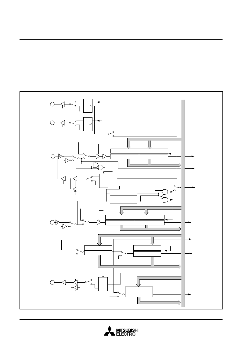
The 3827 group has five timers: timer X, timer Y, timer 1, timer 2,
and timer 3. Timer X and timer Y are 16-bit timers, and timer 1,
timer 2, and timer 3 are 8-bit timers.
All timers are down count timers. When the timer reaches “00
16
”,
an underflow occurs at the next count pulse and the correspond-
ing timer latch is reloaded into the timer and the count is
continued. When a timer underflows, the interrupt request bit cor-
responding to that timer is set to “1”.
Read and write operation on 16-bit timer must be performed for
both high and low-order bytes. When reading a 16-bit timer, read
the high-order byte first. When writing to a 16-bit timer, write the
low-order byte first. The 16-bit timer cannot perform the correct op-
eration when reading during the write operation, or when writing
during the read operation.
Fig. 17 Timer block diagram
相關(guān)PDF資料 |
PDF描述 |
|---|---|
| M38273EEMXXXHP | Automotive Catalog Low-Power Rail-to-Rail Input/Output Operational Amplifier with Shutdown 14-SOIC -40 to 125 |
| M38273M3MXXXHP | SINGLE-CHIP 8-BIT CMOS MICROCOMPUTER |
| M38273M4-XXXFP | Automotive Catalog Low-Power Rail-to-Rail Input/Output Operational Amplifier with Shutdown 14-TSSOP -40 to 125 |
| M38273M4-XXXFS | SINGLE-CHIP 8-BIT CMOS MICROCOMPUTER |
| M38273M4-XXXGP | SINGLE-CHIP 8-BIT CMOS MICROCOMPUTER |
相關(guān)代理商/技術(shù)參數(shù) |
參數(shù)描述 |
|---|---|
| M3828 BK001 | 制造商:Alpha Wire Company 功能描述:CBL 3COND 16AWG BLK 1000' |
| M3828 BK002 | 制造商:Alpha Wire Company 功能描述:CBL 3COND 16AWG BLK 500' |
| M3828 BK005 | 制造商:Alpha Wire Company 功能描述:CBL 3COND 16AWG BLK 100' |
| M3828 BK199 | 制造商:Alpha Wire Company 功能描述:CBL 3COND 16AWG BLK 3000=3000' |
| M3829 BK001 | 制造商:Alpha Wire Company 功能描述:CBL 4COND 16AWG BLK 1000' |
發(fā)布緊急采購,3分鐘左右您將得到回復(fù)。