- 您現(xiàn)在的位置:買賣IC網(wǎng) > PDF目錄370918 > M38271M5MXXXFS (Mitsubishi Electric Corporation) SINGLE-CHIP 8-BIT CMOS MICROCOMPUTER PDF資料下載
參數(shù)資料
| 型號(hào): | M38271M5MXXXFS |
| 廠商: | Mitsubishi Electric Corporation |
| 英文描述: | SINGLE-CHIP 8-BIT CMOS MICROCOMPUTER |
| 中文描述: | 單芯片8位CMOS微機(jī) |
| 文件頁數(shù): | 8/70頁 |
| 文件大?。?/td> | 1112K |
| 代理商: | M38271M5MXXXFS |
第1頁第2頁第3頁第4頁第5頁第6頁第7頁當(dāng)前第8頁第9頁第10頁第11頁第12頁第13頁第14頁第15頁第16頁第17頁第18頁第19頁第20頁第21頁第22頁第23頁第24頁第25頁第26頁第27頁第28頁第29頁第30頁第31頁第32頁第33頁第34頁第35頁第36頁第37頁第38頁第39頁第40頁第41頁第42頁第43頁第44頁第45頁第46頁第47頁第48頁第49頁第50頁第51頁第52頁第53頁第54頁第55頁第56頁第57頁第58頁第59頁第60頁第61頁第62頁第63頁第64頁第65頁第66頁第67頁第68頁第69頁第70頁
8
SINGLE-CHIP 8-BIT CMOS MICROCOMPUTER
3827 Group
MITSUBISHI MICROCOMPUTERS
Not available
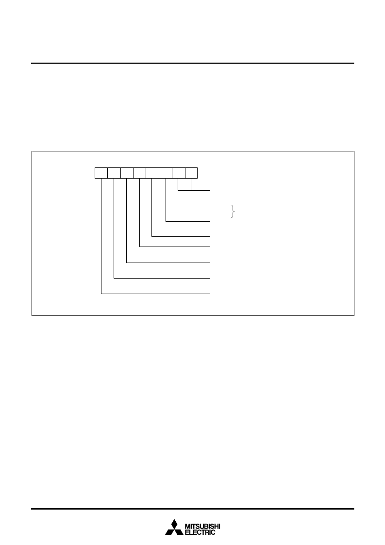
Processor mode bits
b1 b0
0 0 : Single-chip mode
0 1 :
1 0 :
1 1 :
Stack page selection bit
0 : 0 page
1 : 1 page
Not used (returns “1” when read)
(Do not write “0” to this bit.)
Port X
C
switch bit
0 : Stop oscillating
1 : X
CIN
, X
COUT
Main clock ( X
IN
-X
OUT
) stop bit
0 : Oscillating
1 : Stopped
Main clock division ratio selection bit
0 : X
IN
/2 (high-speed mode)
1 : X
IN
/8 (middle-speed mode)
Internal system clock selection bit
0 : X
IN
-X
OUT
selected (middle-/high-speed mode)
1 : X
CIN
-X
COUT
selected (low-speed mode)
CPU mode register
(CPUM (CM) : address 003B
16
)
b7
b0
FUNCTIONAL DESCRIPTION
Central Processing Unit (CPU)
The 3827 group uses the standard 740 family instruction set. Re-
fer to the table of 740 family addressing modes and machine
instructions or the 740 Family Software Manual for details on the
instruction set.
Machine-resident 740 family instructions are as follows:
The FST and SLW instruction cannot be used.
The STP, WIT, MUL, and DIV instruction can be used.
[CPU Mode Register (CPUM)] 003B
16
The CPU mode register contains the stack page selection bit and
the internal system clock selection bit.
The CPU mode register is allocated at address 003B
16
.
Fig. 6 Structure of CPU mode register
相關(guān)PDF資料 |
PDF描述 |
|---|---|
| M38272M5MXXXFS | SINGLE-CHIP 8-BIT CMOS MICROCOMPUTER |
| M38273M5MXXXFS | SINGLE-CHIP 8-BIT CMOS MICROCOMPUTER |
| M38272E5MXXXFS | Single, Low Power, Rail-to-Rail Input/Output Operational Amplifier 5-SOT-23 0 to 70 |
| M38272E5MXXXGP | Single, Low Power, Rail-to-Rail Input/Output Operational Amplifier 5-SOT-23 0 to 70 |
| M38272E5MXXXHP | Single, Low Power, Rail-to-Rail Input/Output Operational Amplifier 5-SOT-23 0 to 70 |
相關(guān)代理商/技術(shù)參數(shù) |
參數(shù)描述 |
|---|---|
| M3828 BK001 | 制造商:Alpha Wire Company 功能描述:CBL 3COND 16AWG BLK 1000' |
| M3828 BK002 | 制造商:Alpha Wire Company 功能描述:CBL 3COND 16AWG BLK 500' |
| M3828 BK005 | 制造商:Alpha Wire Company 功能描述:CBL 3COND 16AWG BLK 100' |
| M3828 BK199 | 制造商:Alpha Wire Company 功能描述:CBL 3COND 16AWG BLK 3000=3000' |
| M3829 BK001 | 制造商:Alpha Wire Company 功能描述:CBL 4COND 16AWG BLK 1000' |
發(fā)布緊急采購,3分鐘左右您將得到回復(fù)。