- 您現在的位置:買賣IC網 > PDF目錄370849 > M37905F8CFP (Mitsubishi Electric Corporation) 16-BIT CMOS MICROCOMPUTER PDF資料下載
參數資料
| 型號: | M37905F8CFP |
| 廠商: | Mitsubishi Electric Corporation |
| 英文描述: | 16-BIT CMOS MICROCOMPUTER |
| 中文描述: | 16位CMOS微機 |
| 文件頁數: | 8/34頁 |
| 文件大小: | 362K |
| 代理商: | M37905F8CFP |
第1頁第2頁第3頁第4頁第5頁第6頁第7頁當前第8頁第9頁第10頁第11頁第12頁第13頁第14頁第15頁第16頁第17頁第18頁第19頁第20頁第21頁第22頁第23頁第24頁第25頁第26頁第27頁第28頁第29頁第30頁第31頁第32頁第33頁第34頁
M37905F8CFP, M37905F8CSP
PRELIMINARY
Notice: This is not a final specification.
Some parametric limits are subject to change.
16-BIT CMOS MICROCOMPUTER
MITSUBISHI MICROCOMPUTERS
8
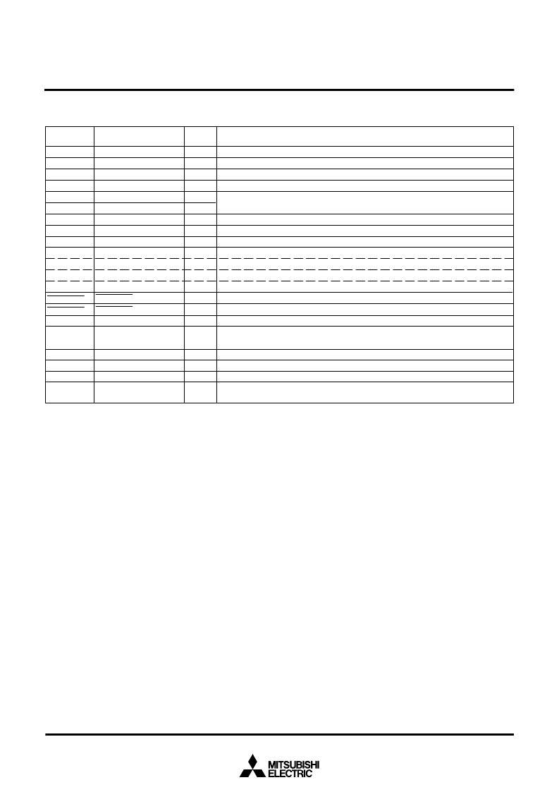
PIN DESCRIPTION (FLASH MEMORY SERIAL I/O MODE)
V
CC
, V
SS
MD0
MD1
RESET
X
IN
X
OUT
AVcc, AVss
V
REF
P1
0
–
P1
7
P2
0
–
P2
3
, P2
7
P2
4
P2
5
P2
6
P4OUT
CUT
P6OUT
CUT
P4
0
–
P4
7
P5
5
–
P5
3,
P5
5
–
P5
7
P6
0
–
P6
7
P7
0
–
P7
4
P8
0
–
P8
3
V
CONT
Pin
Power supply input
MD0
MD1
Reset input
Clock input
Clock output
Analog supply input
Reference voltage input
Input port P1
Input port P2
SCLK input
SDA I/O
BUSY output
P4OUT
CUT
input
P6OUT
CUT
input
Input port P4
Input port P5
Input port P6
Input port P7
Input port P8
Filter circuit connection
Name
—
Input
Input
Input
Input
Output
—
Input
Input
Input
Input
I/O
Output
Input
Input
Input
Input
Input
Input
Input
—
Input
/Output
Functions
Apply 5 V ± 0.5 V to Vcc, and 0 V to Vss.
Connect this pin to Vss.
Connect this pin to Vss via a resistor of 10 k
to 100 k
.
The reset input pin.
Connect a ceramic oscillator between the X
IN
and X
OUT
pins, or input an external
clock from the X
IN
pin with the X
OUT
pin left open.
Connect AVcc to Vcc, and AVss to Vss.
Input an arbitrary level within the range of V
SS
–
V
CC
. (This is not used in the flash memory serial I/O mode.)
Input
“
H
”
or
“
L
”
, or leave them open. (This is not used in the flash memory serial I/O mode.)
Input
“
H
”
or
“
L
”
, or leave them open. (This is not used in the flash memory serial I/O mode.)
This is an input pin for a serial clock.
This is an I/O pin for serial data. Connect this pin to V
CC
via a resistor (about 1 k
).
This is an output pin for the BUSY signal.
Input
“
H
”
.
Input
“
H
”
.
Input
“
H
”
or
“
L
”
, or leave them open. (This is not used in the flash memory serial I/O mode.)
Input
“
H
”
or
“
L
”
, or leave them open. (This is not used in the flash memory serial I/O mode.)
Input
“
H
”
or
“
L
”
, or leave them open. (This is not used in the flash memory serial I/O mode.)
Input
“
H
”
or
“
L
”
, or leave them open. (This is not used in the flash memory serial I/O mode.)
Input
“
H
”
or
“
L
”
, or leave them open. (This is not used in the flash memory serial I/O mode.)
Connect this pin to the filter circuit, or leave this pin open. (This is not used in the flash
memory serial I/O mode.)
相關PDF資料 |
PDF描述 |
|---|---|
| M37905F8CSP | 16-BIT CMOS MICROCOMPUTER |
| M37905M4C | DIODE SCHOTTKY DUAL COMMON-ANODE 25V 200mW 0.32V-vf 200mA-IFM 1mA-IF 2uA-IR SOT-323 3K/REEL |
| M37905M4C-XXXFP | 16 BIT CMOS MICROCOMPUTER |
| M37905M4C-XXXSP | 16 BIT CMOS MICROCOMPUTER |
| M37905M6C-XXXFP | DIODE SCHOTTKY DUAL-DUAL SERIES 25V 200mW 0.32V-vf 200mA-IFM 1mA-IF 2uA-IR SOT-363 3K/REEL |
相關代理商/技術參數 |
參數描述 |
|---|---|
| M37905F8CSP | 制造商:MITSUBISHI 制造商全稱:Mitsubishi Electric Semiconductor 功能描述:16-BIT CMOS MICROCOMPUTER |
| M37905M4C | 制造商:MITSUBISHI 制造商全稱:Mitsubishi Electric Semiconductor 功能描述:16 BIT CMOS MICROCOMPUTER |
| M37905M4C-XXXFP | 制造商:MITSUBISHI 制造商全稱:Mitsubishi Electric Semiconductor 功能描述:16 BIT CMOS MICROCOMPUTER |
| M37905M4C-XXXSP | 制造商:MITSUBISHI 制造商全稱:Mitsubishi Electric Semiconductor 功能描述:16 BIT CMOS MICROCOMPUTER |
| M37905M6C-XXXFP | 制造商:MITSUBISHI 制造商全稱:Mitsubishi Electric Semiconductor 功能描述:16 BIT CMOS MICROCOMPUTER |
發(fā)布緊急采購,3分鐘左右您將得到回復。