- 您現(xiàn)在的位置:買賣IC網(wǎng) > PDF目錄370845 > M37516 (Mitsubishi Electric Corporation) SINGLE-CHIP 8-BIT CMOS MICROCOMPUTER PDF資料下載
參數(shù)資料
| 型號(hào): | M37516 |
| 廠商: | Mitsubishi Electric Corporation |
| 英文描述: | SINGLE-CHIP 8-BIT CMOS MICROCOMPUTER |
| 中文描述: | 單芯片8位CMOS微機(jī) |
| 文件頁(yè)數(shù): | 43/54頁(yè) |
| 文件大?。?/td> | 358K |
| 代理商: | M37516 |
第1頁(yè)第2頁(yè)第3頁(yè)第4頁(yè)第5頁(yè)第6頁(yè)第7頁(yè)第8頁(yè)第9頁(yè)第10頁(yè)第11頁(yè)第12頁(yè)第13頁(yè)第14頁(yè)第15頁(yè)第16頁(yè)第17頁(yè)第18頁(yè)第19頁(yè)第20頁(yè)第21頁(yè)第22頁(yè)第23頁(yè)第24頁(yè)第25頁(yè)第26頁(yè)第27頁(yè)第28頁(yè)第29頁(yè)第30頁(yè)第31頁(yè)第32頁(yè)第33頁(yè)第34頁(yè)第35頁(yè)第36頁(yè)第37頁(yè)第38頁(yè)第39頁(yè)第40頁(yè)第41頁(yè)第42頁(yè)當(dāng)前第43頁(yè)第44頁(yè)第45頁(yè)第46頁(yè)第47頁(yè)第48頁(yè)第49頁(yè)第50頁(yè)第51頁(yè)第52頁(yè)第53頁(yè)第54頁(yè)
43/54
M37516M6-XXXHP
GNOK-M37516M6-XXXHP-50
(MSETSU 2)
PA
GE
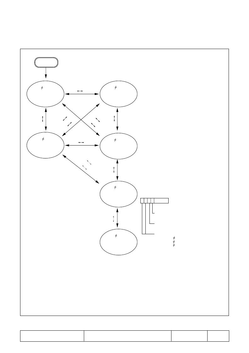
Fig. 52 State transitions of system clock
CM
4
: Port Xc switch bit
0 : I/O port function (stop oscillating)
1 : X
CIN
-X
COUT
oscillating function
CM
5
: Main clock (X
IN
- X
OUT
) stop bit
0 : Oscillating
1 : Stopped
CM
7
, CM
6
: Main clock division ratio selection bit
b7 b6
0 0 :
=
f
(X
IN
)/2 ( High-speed mode)
0 1 :
=
f
(X
IN
)/8 (Middle-speed mode)
1 0 :
=
f
(X
CIN
)/2 (Low-speed mode)
1 1 : Not available
Notes
Reset
C
4
“
“
CM
4
“0
CM
6
“1
“1
“0
CM
4
“1
“0
CM
6
“1
“0
C
7
“
“
C
4
“
“
C
5
“
“
CM
6
“1”
“0”
CM
6
“1”
“0”
CPU mode register
(CPUM : address 003B
16
)
b7
b4
CM
7
“0
CM
6
“1
“1
“0
CM
7
=0
CM
6
=1
CM
5
=0(8 MHz oscillating)
CM
4
=0(32 kHz stopped)
Middle-speed mode
(f(
)=1 MHz)
CM
7
=0
CM
6
=1
CM
5
=0(8 MHz oscillating)
CM
4
=1(32 kHz oscillating)
Middle-speed mode
(f(
)=1 MHz)
CM
7
=0
CM
6
=0
CM
5
=0(8 MHz oscillating)
CM
4
=0(32 kHz stopped)
High-speed mode
(f(
)=4 MHz)
CM
7
=1
CM
6
=0
CM
5
=0(8 MHz oscillating)
CM
4
=1(32 kHz oscillating)
Low-speed mode
(f(
)=16 kHz)
CM
7
=1
CM
6
=0
CM
5
=1(8 MHz stopped)
CM
4
=1(32 kHz oscillating)
Low-speed mode
(f(
)=16 kHz)
CM
7
=0
CM
6
=0
CM
5
=0(8 MHz oscillating)
CM
4
=1(32 kHz oscillating)
High-speed mode
(f(
)=4 MHz)
1 :
Switch the mode by the allows shown between the mode blocks. (Do not switch between the modes directly without an allow.)
2 :
The all modes can be switched to the stop mode or the wait mode and return to the source mode when the stop mode or the wait mode is
ended.
3 :
Timer operates in the wait mode.
4 :
When the stop mode is ended, a delay of approximately 1 ms occurs by connecting Timer 1 in middle/high-speed mode.
5 :
When the stop mode is ended, the following is performed.
(1) After the clock is restarted, a delay of approximately 16ms occurs in low-speed mode if Timer 12 count source selection bit is "0".
(2) After the clock is restarted, a delay of approximately 250ms occurs in low-speed mode if Timer 12 count source selection bit is "1".
6 :
Wait until oscillation stabilizes after oscillating the main clock X
IN
before the switching from the low-speed mode to middle/high-speed
mode.
7 :
The example assumes that 8 MHz is being applied to the X
IN
pin and 32 kHz to the X
CIN
pin. f indicates the internal clock.
相關(guān)PDF資料 |
PDF描述 |
|---|---|
| M37516M6-A30HP | SINGLE-CHIP 8-BIT CMOS MICROCOMPUTER |
| M37516M6-A34HP | SINGLE-CHIP 8-BIT CMOS MICROCOMPUTER |
| M37516M6-A40HP | SINGLE-CHIP 8-BIT CMOS MICROCOMPUTER |
| M37516M6-A46HP | SINGLE-CHIP 8-BIT CMOS MICROCOMPUTER |
| M37516M6-A48KP | SINGLE-CHIP 8-BIT CMOS MICROCOMPUTER |
相關(guān)代理商/技術(shù)參數(shù) |
參數(shù)描述 |
|---|---|
| M37516E1H-XXXKP | 制造商:RENESAS 制造商全稱:Renesas Technology Corp 功能描述:SINGLE-CHIP 8-BIT CMOS MICROCOMPUTER |
| M37516E1-XXXHP | 制造商:RENESAS 制造商全稱:Renesas Technology Corp 功能描述:SINGLE-CHIP 8-BIT CMOS MICROCOMPUTER |
| M37516E1-XXXKP | 制造商:RENESAS 制造商全稱:Renesas Technology Corp 功能描述:SINGLE-CHIP 8-BIT CMOS MICROCOMPUTER |
| M37516E2H-XXXKP | 制造商:RENESAS 制造商全稱:Renesas Technology Corp 功能描述:SINGLE-CHIP 8-BIT CMOS MICROCOMPUTER |
| M37516E2-XXXHP | 制造商:RENESAS 制造商全稱:Renesas Technology Corp 功能描述:SINGLE-CHIP 8-BIT CMOS MICROCOMPUTER |
發(fā)布緊急采購(gòu),3分鐘左右您將得到回復(fù)。